
Rotary Valve for Cement, Fly Ash and Powder Handling
Dust-Tight Rotary Airlock Feeder for Silos, Hoppers and Dust Collectors
Rotary Valve Product Overview
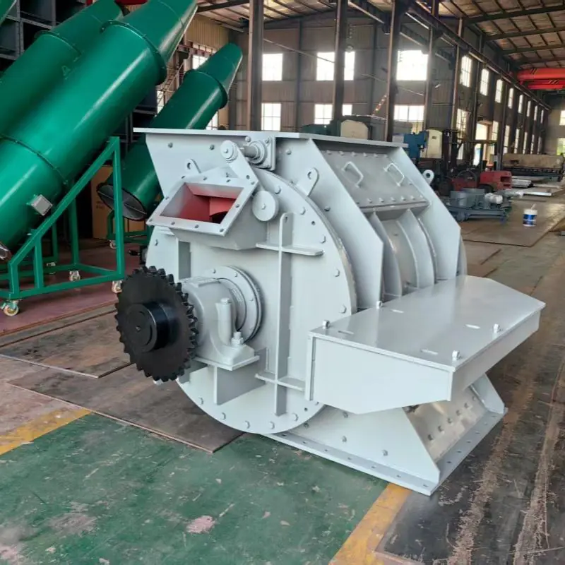
The rotary valve contains a multi-blade rotor that divides the internal chamber into several material pockets. As the rotor turns, material enters through the upper inlet, fills the rotor pockets and is transferred to the lower outlet.
The close clearance between the rotor blades and the valve housing restricts direct airflow through the equipment. This allows the rotary valve to discharge material continuously while helping maintain pressure stability in the connected system.
| Product Name | Main Meaning | Typical Application |
|---|---|---|
| Rotary Valve | General product name | Powder and granular material discharge |
| Rotary Airlock Valve | Emphasizes air sealing | Pneumatic conveying and dust collection |
| Rotary Feeder | Emphasizes continuous feeding | Controlled feeding into downstream equipment |
| Star Discharge Valve | Refers to the star-shaped rotor | Silo, hopper and dust collector discharge |
| Airlock Feeder | Combines feeding and pressure isolation | Pressure or vacuum systems |
These terms usually describe the same equipment category. However, the rotor, sealing system and internal clearance must still be selected according to the actual operating conditions.
Main Features
✅ Continuous discharge of powder and granular materials
✅ Reduced air leakage and pressure loss
✅ Stable material transfer below silos and hoppers
✅ Dust-tight discharge below bag filters and dust collectors
✅ Multiple rotor designs for different materials and operating conditions
✅ Cast iron, carbon steel, SS304 and SS316 construction options
✅ Wear-resistant rotor blades available for abrasive powders
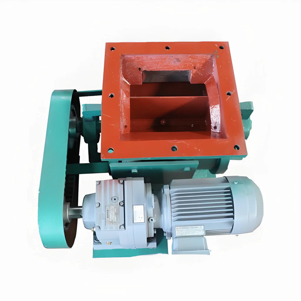
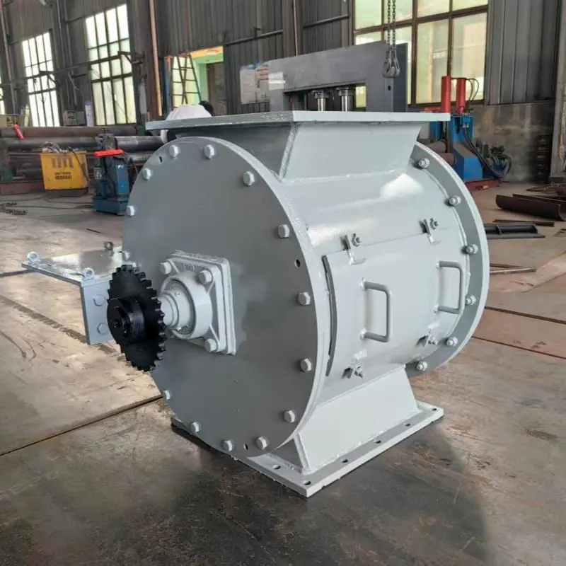
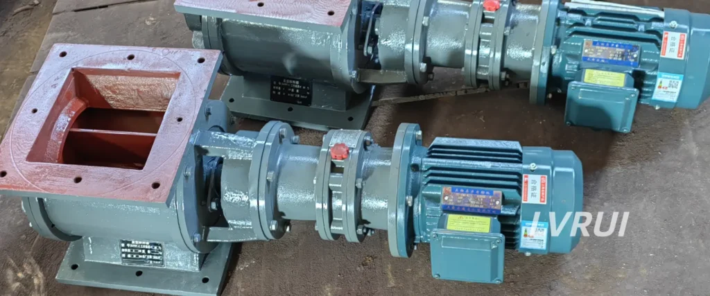
✅ Direct gear motor, chain drive and customized drive arrangements
✅ Optional variable-frequency control for adjustable feeding
✅ Multiple shaft sealing options for fine powder applications
✅ Customized flange dimensions, installation height and motor voltage
✅ Replaceable seals, bearings and wear components for easier maintenance
How Does a Rotary Valve Work?
Material enters the rotary valve through the upper inlet and fills the empty pockets between the rotor blades. The gear motor rotates the rotor at a controlled speed, carrying the material around the internal housing.
When each filled pocket reaches the lower outlet, the material falls into the downstream equipment by gravity. The empty pocket then returns to the inlet and repeats the cycle.
| Function | Description |
|---|---|
| Continuous Discharge | Material is transferred continuously through rotating pockets |
| Airlock Function | Rotor and housing restrict direct airflow |
| Controlled Feeding | Rotor volume and speed determine approximate output |
| Dust Isolation | Enclosed structure reduces uncontrolled dust release |
| Pressure Separation | Helps maintain pressure differences between connected equipment |
A rotary valve is not a completely airtight shut-off valve. Some air leakage remains through the rotor clearances and empty returning pockets.
Actual leakage depends on:
✅ Rotor clearance
✅ Pressure difference
✅ Valve size
✅ Rotor speed
✅ Rotor design
✅ Material loading
✅ Wear condition
Available Rotor Types
| Rotor Type | Main Characteristics | Suitable Application |
|---|---|---|
| Open-End Rotor | Simple structure and good material release | General powder and granular discharge |
| Closed-End Rotor | Better separation from the end plates | Fine powder and improved airlock performance |
| Adjustable-Tip Rotor | Replaceable or adjustable blade tips | Cement, fly ash and abrasive powder |
| Customized Rotor | Application-specific internal structure | Sticky, hot, abrasive or special materials |
For abrasive materials, an adjustable-tip rotor is often preferred because worn blade tips can be replaced or adjusted without replacing the complete rotor.
Proper rotor selection affects material flow, air leakage, wear rate and rotary valve service life. More information is available in this guide to rotary airlock valve principles and rotor design.
Housing Materials
| Material | Main Advantages | Typical Application |
|---|---|---|
| Cast Iron | Good rigidity and economical construction | General dry powder handling |
| Carbon Steel | Strong and easy to customize | Cement, fly ash and mineral powder |
| Stainless Steel 304 | Improved corrosion resistance | Cleaner or mildly corrosive applications |
| Stainless Steel 316 | Higher corrosion resistance | More demanding chemical environments |
The correct housing material should be selected according to the material abrasiveness, corrosiveness, temperature, cleaning requirements and expected service life.
Typical Technical Specifications
| Item | LRB150 | LRB200 | LRB300 | LRB400 | LRB500 |
|---|---|---|---|---|---|
| Nominal Inlet Size | 150 × 150 mm | 200 × 200 mm | 300 × 300 mm | 400 × 400 mm | 500 × 500 mm |
| Reference Capacity | 3-8m³/h | 9-15 m³/h | 16-30 m³/h | 32-40 m³/h | 40–60 m³/h |
| Reference Rotor Speed | 10–30 rpm | 10–30 rpm | 10–30 rpm | 10–30 rpm | 10–30 rpm |
| Reference Motor Power | 0.55 kW | 0.75 kW | 1.5 kW | 2.2 kW | 4 kW |
| Housing Material | Cast Iron / Carbon Steel / SS304 | Cast Iron / Carbon Steel / SS304 | Cast Iron / Carbon Steel / SS304 | Cast Iron / Carbon Steel / SS304 | Cast Iron / Carbon Steel / SS304 |
| Rotor Type | Customized | Customized | Customized | Customized | Customized |
| Drive Type | Direct / Chain Drive | Direct / Chain Drive | Direct / Chain Drive | Direct / Chain Drive | Direct / Chain Drive |
| Suitable Material | Powder / Granule | Powder / Granule | Powder / Granule | Powder / Granule | Powder / Granule |
The values above are reference configurations rather than guaranteed operating capacities.
Actual capacity depends on:
| Capacity Factor | Influence |
|---|---|
| Rotor Pocket Volume | Determines volume transferred per revolution |
| Rotor Speed | Determines the number of transfer cycles |
| Filling Efficiency | Reduces theoretical capacity |
| Material Bulk Density | Converts volume into mass output |
| Material Flowability | Affects pocket filling |
| Pressure Difference | Can influence material entry and discharge |
| Material Aeration | May reduce effective bulk density |
The inlet size, outlet size, rotor structure, motor power, construction material and flange dimensions can be customized.
Applications
✅ Baghouse / dust collector discharge (dust-tight airlock under hopper)
✅ Cyclone separator discharge and air balance control
✅ Silo & hopper feeding to screw conveyor / air slide / pneumatic line
✅ Cement plant raw mill, kiln, clinker handling and cement dispatch systems
✅ Power plant fly ash handling and pneumatic transport
Typical Installation Positions
| Installation Position | Function |
|---|---|
| Below a Cement Silo | Continuous cement discharge |
| Below a Fly Ash Hopper | Stable fine-powder feeding |
| Below a Bag Filter | Dust discharge with limited air entry |
| Below a Cyclone | Material discharge while maintaining pressure |
| Above a Screw Conveyor | Controlled material feeding |
| Before a Pneumatic Line | Feeding into pressure or vacuum conveying |
A slide gate valve is recommended above the rotary valve when material must be isolated during maintenance.
Where compacted lumps may enter from the silo, a lump breaker or screen should be installed upstream. A rotary valve should not be used to crush hardened material.
Rotary Valve Selection Guide
The rotary valve should not be selected only according to the silo outlet size.
| Required Information | Details |
|---|---|
| Material | Cement, fly ash or other powder |
| Required Capacity | t/h or m³/h |
| Bulk Density | kg/m³ or t/m³ |
| Particle Size | Minimum and maximum size |
| Material Condition | Free-flowing, cohesive or abrasive |
| Temperature | Material operating temperature |
| System Pressure | Pressure or vacuum |
| Installation Position | Silo, hopper, filter or pipeline |
| Connection Size | Inlet and outlet dimensions |
| Motor Supply | Voltage, frequency and phase |
For pneumatic conveying applications, the pressure difference, rotor clearance, shaft seal and air leakage must be considered carefully.
Why Choose LVRUI?
| LVRUI Capability | Customer Value |
|---|---|
| Application-Based Selection | Correct valve for actual working conditions |
| Customized Rotor Design | Better material compatibility |
| Wear-Resistant Options | Longer operating life |
| Multiple Shaft Seals | Reduced fine-powder leakage |
| Flexible Drive Design | Easier installation |
| Custom Motor Voltage | Suitable for overseas projects |
| Technical Drawing Support | Faster project confirmation |
| System Equipment Supply | Compatible silo and conveying equipment |
FAQs About Rotary Valve
What is a rotary valve?
A rotary valve is a bulk material handling device used to discharge powder or granules continuously through a rotating multi-pocket rotor. The close clearance between the rotor and housing limits direct airflow, allowing the valve to transfer material while maintaining a degree of pressure separation between connected equipment.
Is a rotary valve the same as a rotary airlock valve?
The terms are often used for the same type of equipment. “Rotary valve” is the general product name, while “rotary airlock valve” places more emphasis on limiting air leakage between areas operating at different pressures. The actual airlock performance depends on rotor clearance, pressure difference, rotor design and wear condition.
Is a star discharge valve the same as a rotary valve?
In most cement and powder handling applications, yes. A star discharge valve is another name for a rotary valve because the internal multi-blade rotor resembles a star. It may also be called a rotary feeder or airlock feeder, depending on whether the main function is material feeding or pressure isolation.
Can a rotary valve handle cement and fly ash?
Yes. Rotary valves are commonly used for cement, fly ash, limestone powder, lime and other dry bulk materials. For fine or abrasive powder, the valve may require wear-resistant rotor tips, suitable shaft seals and carefully selected internal clearance.
Can a rotary valve be installed below a dust collector?
Yes. A dust collector rotary valve can be installed below a bag filter, cyclone or dust hopper to discharge collected powder while limiting uncontrolled air entry. The rotor and shaft seal should be selected according to the system pressure and dust characteristics.
Can a rotary valve control material flow?
A rotary valve can provide approximate volumetric feeding because each rotor pocket carries a defined volume of material. The output can be adjusted by changing the rotor speed with a variable-frequency drive. For high-accuracy dosing, the valve should be combined with a weighing and control system.
Can a rotary valve completely stop airflow?
No. A rotary valve restricts airflow but is not a zero-leakage shut-off valve. Air can pass through the clearance between the rotor and housing and through empty returning rotor pockets. Leakage increases when the rotor becomes worn or the pressure difference is too high.
How do I select the correct rotary valve?
Selection should be based on the required capacity, material bulk density, particle size, flowability, abrasiveness, temperature, system pressure and installation dimensions. The correct rotor type, shaft seal, construction material and motor configuration should be confirmed before production.
Need a Rotary Valve for Your Powder System?
Partner with LVRUI for professional bulk material handling solutions and responsive technical support.
✅ Get expert quotation and customized solution within 12 hours.
✅ Factory direct supply with strict quality control
✅ Professional engineering support from experienced team
✅ Stable delivery for overseas industrial projects