
Flow Control Gate Valve for Cement Silo and Bulk Powder Handling
Reliable Flow Control Gate Valve for Powders & Granular Materials
What Is a Flow Control Gate Valve?
A flow control gate valve is designed to control the discharge of dry bulk materials from a silo, hopper, bin, chute, or conveying system. Unlike a simple shut-off valve, it can be used not only for opening and closing the material flow, but also for adjusting the discharge rate according to process requirements.
In cement and powder handling systems, uncontrolled material discharge may cause feeding surges, unstable conveying, dust leakage, weighing errors, equipment blockage, or excessive wear on downstream machines. A properly selected flow control gate valve helps operators achieve smoother material discharge and better process stability.
It is commonly installed around silo discharge, conveyor feeding, batching and bulk loading systems, including:
✅ Cement silo outlet
✅ Fly ash silo outlet
✅ Hopper bottom
✅ Pneumatic conveying line inlet
✅ Screw conveyor inlet
✅ Bulk loader feeding point
✅ Weighing hopper
✅ Batching system
✅ Cement packing or loading system
✅ Powder transfer chute
For cement plants, fly ash terminals, grinding stations, and dry powder handling projects, a flow control gate valve is often used together with air slide conveyors, screw conveyors, lump breakers, bulk loaders, bag filters, and other bulk material handling equipment.
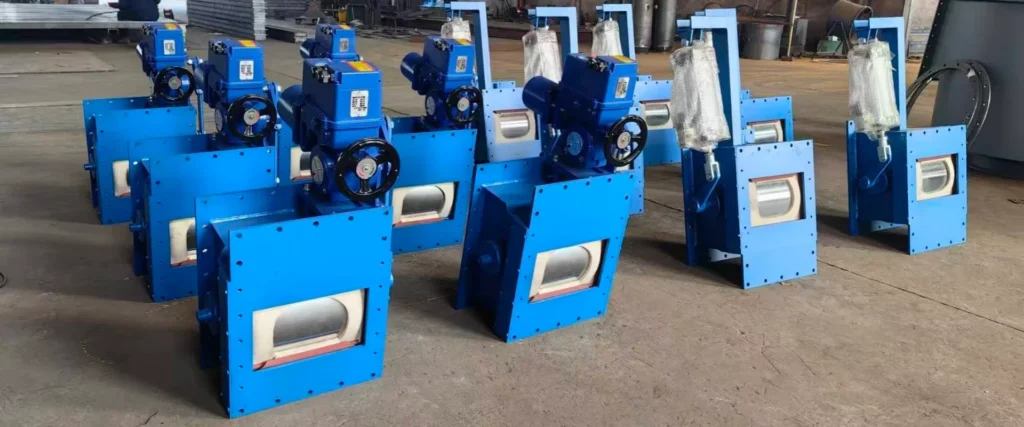
Key Engineering Benefits of LVRUI Flow Control Gate Valves
| Benefit | What It Means for Cement and Powder Systems |
|---|---|
| Adjustable powder discharge | Helps regulate the material flow from cement silos, hoppers, bins, and powder storage systems. |
| Stable downstream feeding | Reduces sudden material surges before air slide conveyors, screw conveyors, loading spouts, weighing systems, or batching equipment. |
| Multiple operation options | Manual, pneumatic, and motorized types are available for local operation, frequent switching, or automated flow regulation. |
| Dust-controlled operation | Supports better sealing at discharge points when used with proper silo sealing, connection design, and dust collection systems. |
| Custom inlet sizes | Standard and customized inlet sizes are available according to silo outlet dimensions and project layout. |
| Suitable for dry bulk materials | Can be used for cement, fly ash, lime powder, gypsum, limestone powder, clinker powder, and other dry powder materials. |
| Integration with conveying systems | Can be installed with air slide conveyors, screw conveyors, bulk loaders, and silo discharge systems. |
| Custom structure design | Valve body, sealing structure, flange interface, actuator type, and material selection can be adjusted according to working conditions. |
How Does a Flow Control Gate Valve Work?
A flow control gate valve controls material flow by changing the effective opening area between the silo outlet and the downstream equipment. When the valve opening increases, more material can pass through. When the opening decreases, the material flow rate is reduced. When fully closed, the valve can isolate the material discharge point for equipment maintenance or process control.
Depending on the design and project requirement, the flow adjustment can be achieved by a sliding gate plate, rotary opening structure, manual handwheel, pneumatic cylinder, or electric actuator.
For automated cement plant systems, pneumatic or motorized flow control gates can be connected with limit switches, position indicators, PLC signals, or proportional control systems. This allows operators to control material discharge remotely from a control room or integrate the valve into a complete production line.
A good flow control gate valve should not only open and close smoothly. It should also consider powder flow behavior, sealing performance, material abrasiveness, installation space, actuator reliability, and maintenance access.
Main Types of Flow Control Gate Valves
LVRUI supplies three common operation types: manual flow control gate valves, pneumatic flow control gate valves, and motorized flow control gate valves.
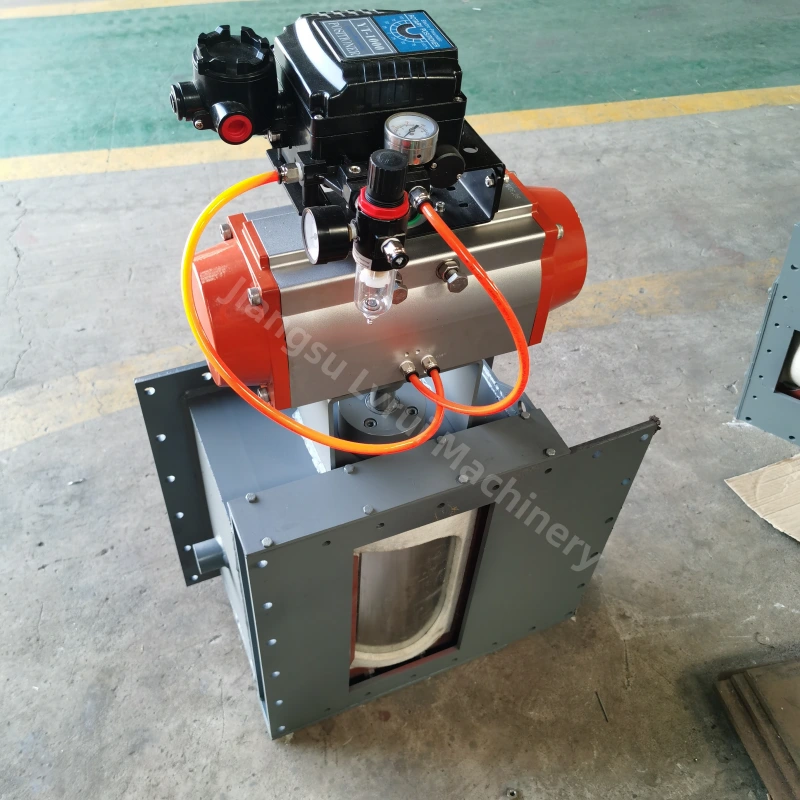
Pneumatic Flow Control Gate (air-operated slide gate)
Pneumatic flow control gates are ideal for automated systems where fast response and frequent cycling are required. They are widely used in cement grinding stations, silo discharge lines, and powder dosing systems.
A pneumatic flow control gate is driven by an air cylinder and designed for fast opening and closing.
✅ Quick response and stable movement
✅ Suitable for frequent switching operations
✅ Ideal for powder and granular material
✅ Low maintenance, long service life
Motorized Flow Control Gate (electric actuator type)
Motorized flow control gates offer precise opening control with adjustable speed, making them suitable for batching systems, clinker lines, and heavy-duty conveying operations.
A motorized flow control gate uses an electric motor and screw drive to precisely adjust the opening position.
✅ Accurate flow control and adjustable speed
✅ Best for continuous dosing and metering
✅ Smooth and stable operation
✅ Easy integration with automation systems
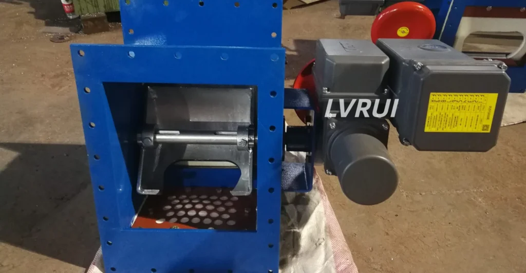
Manual Flow Control Gate (handwheel operated)
Manual flow control gates are designed for precise on-site adjustment of bulk material flow without requiring any power supply. They are widely used at silo outlets, chute bottoms, hoppers, and bulk discharge points.
A manual flow control gate valve uses a handwheel or lever to manually adjust the opening size, allowing precise control of powder or granular material flow.
✅ Suitable for powder & granular materials
✅ No electricity required (ideal for remote locations)
✅ Low maintenance and long service life
Manual vs Pneumatic vs Motorized Flow Control Gate Valve
| Type | Operation Method | Best For | Main Advantage | Limitation |
|---|---|---|---|---|
| Manual flow control gate valve | Handwheel or manual mechanism | Low-frequency operation, simple discharge control, maintenance isolation | Simple structure, easy operation, lower cost | Not suitable for frequent remote operation |
| Pneumatic flow control gate valve | Pneumatic cylinder | Frequent open-close operation, remote control, automated silo discharge | Fast response, convenient for production lines | Requires compressed air supply |
| Motorized flow control gate valve | Electric actuator or motorized drive | Proportional flow control, batching, weighing, PLC system | Better opening control and automation compatibility | Higher cost and more electrical control requirements |
If the valve is mainly used for maintenance isolation or occasional adjustment, manual operation is usually enough. If the valve needs frequent open-close action, pneumatic operation is more practical. If the system requires more accurate discharge regulation, remote control, or PLC integration, motorized operation is usually more suitable.
Where Is a Flow Control Gate Installed?
A flow control gate valve can be installed in different positions of a cement or powder handling system. The correct installation position depends on material characteristics, process purpose, available space, downstream equipment, and maintenance requirements.
| Installation Position | Function |
|---|---|
| Under cement silo | Controls cement discharge from the silo outlet before conveying or loading equipment. |
| Under fly ash silo | Regulates fly ash discharge and reduces sudden material surges. |
| Under hopper or bin | Controls powder or granular material discharge from storage equipment. |
| Before air slide conveyor | Adjusts material feeding rate into the air slide conveyor. |
| Before screw conveyor | Prevents uncontrolled feeding and helps protect the screw conveyor from overload. |
| Before bulk loader | Controls the material feeding rate during truck, railcar, or ship loading. |
| Before weighing hopper | Helps improve feeding stability for batching or weighing processes. |
| At transfer point | Used as a shut-off or regulating device between two equipment sections. |
For silo discharge systems with material lumps or blockage risk, a lump breaker can be installed before the flow control gate valve to reduce oversized lumps and protect downstream conveying equipment.
Suitable Materials
LVRUI flow control gate valves are mainly used for dry bulk materials and powder handling applications.
| Material | Application Notes |
|---|---|
| Cement | Commonly used under cement silos, grinding stations, and loading systems. |
| Fly ash | Suitable for fly ash storage and pneumatic or mechanical conveying systems. |
| Lime powder | Requires attention to sealing and material flow characteristics. |
| Gypsum powder | Suitable for dry gypsum powder discharge and transfer systems. |
| Limestone powder | Suitable for mineral powder handling and silo discharge applications. |
| Clinker powder | Requires consideration of abrasiveness and wear-resistant structure. |
| Raw meal | Used in cement plant material handling and process feeding systems. |
| Dry mineral powder | Custom design may be required according to abrasiveness and particle size. |
This valve is mainly designed for dry and flowable bulk materials. For wet, sticky, highly cohesive, or severely lumpy materials, the material condition should be confirmed before selection.
Engineering Selection Guide
Selecting the correct flow control gate valve is not only about choosing an inlet size. The material condition, flow capacity, installation position, actuator type, sealing requirement, and downstream equipment all affect valve performance.
| Selection Factor | Why It Matters |
|---|---|
| Material type | Cement, fly ash, lime powder, gypsum, and clinker powder have different flow behavior and abrasiveness. |
| Bulk density | Affects the actual discharge capacity and load on the valve structure. |
| Required capacity | Determines the suitable valve opening size and flow control range. |
| Silo outlet size | Determines the inlet dimension, flange connection, and installation interface. |
| Particle size | Oversized lumps may cause jamming or unstable discharge. |
| Moisture condition | Wet or sticky material can increase blockage risk. |
| Working temperature | Higher temperature may require special material, sealing, or structural design. |
| Operation frequency | Frequent operation usually requires pneumatic or motorized drive instead of manual operation. |
| Automation level | PLC control, remote operation, position feedback, and limit switch requirements should be confirmed. |
| Downstream equipment | Air slide conveyors, screw conveyors, loading spouts, and weighing systems require different feeding stability. |
| Dust sealing requirement | Discharge points with dust leakage risk may require enhanced sealing and dust collection design. |
| Maintenance space | The valve should allow convenient inspection, adjustment, and replacement of wearing parts. |
Technical Specifications
The following specifications are for preliminary selection only. Actual capacity depends on material type, bulk density, moisture condition, silo outlet design, valve opening, and downstream equipment. Final valve size, actuator type, material, flange connection, and control design should be confirmed according to project drawings and working conditions.
| Item | B250 | B300 | B400 | B500 | B630 |
|---|---|---|---|---|---|
| Inlet Size (mm) | 250×250 | 300×300 | 400×400 | 500×500 | 630×630 |
| Flow Capacity (t/h) | 0–150(max) | 0–220(max) | 0–410(max) | 0–550(max) | 0–700(max) |
| Operation Type | Manual / Pneumatic / Electric | Manual / Pneumatic / Electric | Manual / Pneumatic / Electric | Manual / Pneumatic / Electric | Manual / Pneumatic / Electric |
| Body Material | Carbon Steel | Carbon Steel | Carbon Steel | Carbon Steel | Carbon Steel |
| Working Temperature (°C) | ≤150°C Standard / ≤180°C Optional | ≤150°C Standard / ≤180°C Optional | ≤150°C Standard / ≤180°C Optional | ≤150°C Standard / ≤180°C Optional | ≤150°C Standard / ≤180°C Optional |
| Suitable Materials | Cement/ powder material | Cement/ powder material | Cement/ powder material | Cement/ powder material | Cement/ powder material |
Custom sizes and non-standard flange interfaces are available for silo discharge systems, air slide conveyor inlets, screw conveyor inlets, bulk loading systems, and other cement plant applications.
Structure and Material Options
The structure of a flow control gate valve can be customized according to working conditions and project requirements.
| Option | Available Design |
|---|---|
| Valve body | Carbon steel, stainless steel, or customized wear-resistant structure |
| Inlet size | B250, B300, B400, B500, B630, or custom size |
| Drive type | Manual handwheel, pneumatic cylinder, electric actuator, motorized control |
| Sealing design | Standard sealing, enhanced dust sealing, replaceable sealing strip |
| Control option | Local operation, remote operation, limit switch, position feedback, PLC-compatible control |
| Connection type | Square flange, round flange, customized interface for silo outlet or conveyor inlet |
| Surface treatment | Painting or customized surface protection according to project requirement |
| Wear protection | Optional wear-resistant plate or reinforced structure for abrasive materials |
| Maintenance design | Inspection and maintenance access can be considered according to installation space |
For abrasive materials such as clinker powder, limestone powder, and mineral powder, the valve body and internal contact parts should be selected carefully to improve service life.
Common Problems Solved by Flow Control Gate Valves
A properly selected flow control gate valve can help improve the stability of cement and powder handling systems.
| Common Problem | How the Valve Helps |
|---|---|
| Uncontrolled silo discharge | Adjusts the opening area to regulate material flow from the silo outlet. |
| Sudden feeding surge | Reduces unstable material flow before air slide conveyors, screw conveyors, or weighing systems. |
| Dust leakage at discharge point | Supports dust-controlled operation when combined with proper sealing and dust collection equipment. |
| Overloading downstream equipment | Helps control feeding rate before conveyors, bulk loaders, or batching systems. |
| Difficult maintenance isolation | Can be closed to isolate the discharge point before inspection or maintenance. |
| Inaccurate batching or weighing | Provides more stable feeding before weighing hoppers or batching systems. |
| Material jamming | Correct valve structure and proper upstream material treatment can reduce jamming risk. |
| Poor system integration | Custom flange, actuator, and control options help match the valve with existing equipment. |
A flow control gate valve cannot solve every material flow problem alone. If the material contains large lumps, has high moisture, or frequently bridges inside the silo, the system may also require a lump breaker, air slide conveyor, aeration system, or improved silo discharge design.
For dusty or potentially combustible powder handling environments, valve sealing should be considered together with silo connection design, dust collection equipment, and site safety requirements. You may refer to OSHA’s combustible dust control guidance for general workplace dust hazard information.
System Integration with Related Equipment
A flow control gate valve often works as part of a complete bulk material handling system instead of a single isolated machine.
With Air Slide Conveyor
When installed before an air slide conveyor, the flow control gate valve helps regulate the feeding rate and reduce unstable material flow into the chute. This is important for cement, fly ash, and dry powder conveying systems.
With Screw Conveyor
When installed before a screw conveyor, the valve can help prevent sudden material surges and reduce the risk of screw conveyor overload.
With Bulk Loader
When installed before a bulk loader or loading spout, the valve helps control the material feeding rate during truck, railcar, or ship loading.
With Lump Breaker
If the material contains lumps or hardened blocks, a lump breaker can be installed before the flow control gate valve to protect the valve and downstream conveying equipment.
With Bag Filter
For dusty discharge points, the valve should be used together with proper sealing and dust collection equipment to reduce dust leakage during material transfer.
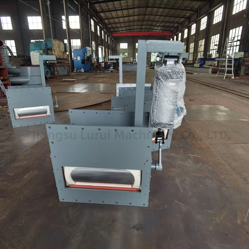
Information Required for Flow Control Gate Valve Quotation
To recommend the correct flow control gate valve, please provide the following project information. This helps our engineers confirm the valve size, actuator type, sealing design, material selection, connection dimensions, and control requirements.
| Required Information | Example |
|---|---|
| Material to be handled | Cement, fly ash, lime powder, gypsum, limestone powder, clinker powder |
| Bulk density | t/m³ or kg/m³ |
| Required capacity | t/h or m³/h |
| Silo outlet size | 250 × 250 mm, 400 × 400 mm, 630 × 630 mm, or custom size |
| Installation position | Silo outlet, hopper bottom, air slide inlet, screw conveyor inlet, loading spout inlet |
| Operation mode | Manual, pneumatic, motorized, PLC-controlled |
| Working temperature | Normal temperature or high-temperature material |
| Dust sealing requirement | Standard sealing or enhanced dust sealing |
| Downstream equipment | Air slide conveyor, screw conveyor, bulk loader, weighing hopper, batching system |
| Control requirement | Local control, remote control, limit switch, position feedback, PLC signal |
| Drawing available? | Yes / No |
| Destination country | For packing, voltage, documentation, and shipping reference |
If you are not sure which model is suitable, you can send your silo outlet size, material name, capacity requirement, and installation photos or drawings. LVRUI will help check the suitable valve type for your project.
Flow Control Gate Valve vs Slide Gate Valve
Although both valves can be used in bulk material handling systems, their purposes are different.
| Item | Flow Control Gate Valve | Slide Gate Valve |
|---|---|---|
| Main function | Regulates, starts, stops, or adjusts material flow | Mainly opens or closes material flow |
| Flow adjustment | Better for adjustable discharge control | Limited flow regulation ability |
| Typical application | Cement silo discharge, air slide feeding, weighing system, bulk loading system | Simple shut-off, maintenance isolation, emergency closing |
| Automation option | Manual, pneumatic, motorized, PLC-compatible | Manual, pneumatic, or electric open-close operation |
| Best for | Systems requiring stable feeding or controlled discharge | Systems requiring simple isolation |
| Selection focus | Capacity, control accuracy, sealing, actuator, material flow behavior | Opening size, shut-off reliability, sealing, operation method |
Choose a flow control gate valve when your system requires adjustable powder discharge, stable feeding, or proportional flow regulation. Choose a slide gate valve when the main purpose is simple open-close isolation for maintenance, emergency shut-off, or basic discharge control.
Why Choose LVRUI Flow Control Gate Valves?
LVRUI focuses on cement bulk material handling equipment, including silo discharge, powder conveying, flow control, dust collection, and bulk loading systems. For flow control gate valve projects, we do not only consider the valve itself, but also the upstream silo outlet, material flow condition, downstream conveyor, loading equipment, and site installation requirements.
According to project drawings and working conditions, LVRUI can help adjust the valve size, actuator type, flange connection, sealing structure, and related equipment configuration. This makes the flow control gate valve easier to integrate with air slide conveyors, screw conveyors, bulk loaders, lump breakers, bag filters, and other cement plant equipment.
FAQs About Flow Control Gates for Cement and Powder Handling
What is a flow control gate valve used for?
A flow control gate valve is used to start, stop, or regulate the discharge of dry bulk materials from silos, hoppers, bins, and powder conveying systems. It is commonly used for cement, fly ash, lime powder, gypsum, limestone powder, and other dry bulk materials.
Where is a flow control gate valve usually installed?
It is usually installed under cement silos, fly ash silos, hopper outlets, air slide conveyor inlets, screw conveyor inlets, bulk loader feeding points, weighing hoppers, or batching systems.
What is the difference between a flow control gate valve and a slide gate valve?
A flow control gate valve is used for adjustable discharge and flow regulation. A slide gate valve is mainly used for simple open-close shut-off or maintenance isolation. If the system requires stable feeding or proportional discharge control, a flow control gate valve is usually more suitable.
Should I choose manual, pneumatic, or motorized operation?
Manual operation is suitable for low-frequency adjustment or simple shut-off. Pneumatic operation is suitable for frequent open-close control and remote operation. Motorized operation is suitable for systems requiring better opening control, PLC integration, batching, or weighing applications.
Can a flow control gate valve be used under a cement silo?
Yes. Cement silo discharge is one of the most common applications. The valve can be installed under the silo outlet to control material discharge before air slide conveyors, screw conveyors, bulk loaders, weighing hoppers, or other downstream equipment.
Can it be used with an air slide conveyor?
Yes. A flow control gate valve can be installed before the air slide conveyor inlet to regulate the feeding rate and improve conveying stability. This is common in cement, fly ash, and dry powder conveying systems.
Can a flow control gate valve work with a bulk loader?
Yes. It can be installed before a bulk loader or loading spout to control the material feeding rate during truck, railcar, or ship loading. For dust-controlled loading systems, it should be used together with proper sealing and dust collection equipment.
What materials can this valve handle?
It is suitable for dry bulk materials such as cement, fly ash, lime powder, gypsum powder, limestone powder, clinker powder, raw meal, and other dry mineral powders. For wet, sticky, or severely lumpy materials, the working condition should be confirmed before selection.
What causes a flow control gate valve to jam?
Jamming may be caused by wet material, oversized lumps, poor silo flow, insufficient clearance, material buildup, unsuitable sealing structure, or incorrect valve selection. If the material contains lumps, a lump breaker may be required before the valve.
Can the valve reduce dust leakage?
The valve can support dust-controlled operation when properly connected with silo outlets, conveying equipment, sealing components, and dust collection systems. For dusty materials such as cement and fly ash, sealing design and system layout should be considered together.
Can the valve be customized?
Yes. The inlet size, flange connection, valve body material, actuator type, sealing structure, control option, and installation interface can be customized according to project requirements.
What information should I provide before asking for a quotation?
Please provide the material name, required capacity, silo outlet size, installation position, operation mode, working temperature, downstream equipment, and destination country. If available, drawings, photos, or layout information are also helpful.
Ready to Get a Reliable Flow Control Solution?
Partner with LVRUI for professional bulk material handling solutions and responsive technical support.
✅ Get expert quotation and customized solution within 12 hours.
✅ Factory direct supply with strict quality control
✅ Professional engineering support from experienced team
✅ Stable delivery for overseas industrial projects