
Pneumatic Flow Control Gate Valve for Cement Silos & Bulk Materials
Precise, Fast & Reliable Pneumatic Discharge Control
What Is an Pneumatic Flow Control Gate?
The Pneumatic Flow Control Gate Valve is a high-performance pneumatic discharge control device designed for accurate regulation of dry bulk material flow in industrial powder handling systems.
It is widely installed beneath cement silos, hoppers, fly ash storage units, limestone powder feeding lines, and pneumatic conveying installations, ensuring stable flow control, reliable dust sealing, and safe operation.
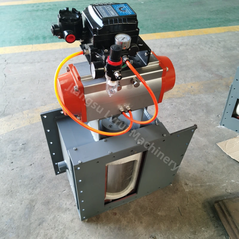
Driven by a pneumatic actuator, the sliding gate plate responds quickly to control signals, enabling consistent material discharge while maintaining effective sealing. This type of automated discharge valve is commonly selected for continuous powder handling processes where flow stability, operational safety, and minimal leakage are critical.
Learn more about the working principles of pneumatic conveying systems from Britannica’s technical overview of pneumatic conveyors.
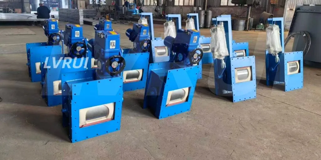
Features
✅ Pneumatic actuation enables accurate and repeatable regulation of bulk material discharge rates
✅ High sealing performance to prevent dust leakage
✅ Heavy-duty steel structure for long service life used in cement bulk handling systems
✅ Smooth slide plate for stable operation
✅ Suitable for cement, fly ash, limestone and powder materials
✅ Easy installation under silos and hoppers
✅ Low maintenance and energy efficient design
Typical Industrial Applications
This valve solution is commonly installed in industrial powder handling processes that require controlled discharge, dust isolation, and stable downstream conveying.
This type of pneumatic discharge control valve is widely used in:
✅ Cement Silos
✅ Fly Ash Storage Systems
✅ Bulk Powder Handling Conveying Lines
✅ Limestone Feeding Systems
✅ Clinker Discharge Units
✅ Industrial Mixing Plants
✅ Dust Collection and Pneumatic Conveying Systems
Working Principle
The pneumatic flow control gate operates through a pneumatic cylinder that drives the slide gate to open or close.
✅ Material enters the gate from the silo or hopper
✅ The pneumatic actuator controls gate opening for accurate flow regulation
✅ When closed, the airtight sealing structure prevents dust escape and material leakage
✅ Continuous and stable discharge is achieved while maintaining system pressure balance
For a basic explanation of powder flow behavior and material characteristics, refer to the Wikipedia overview of powder materials.
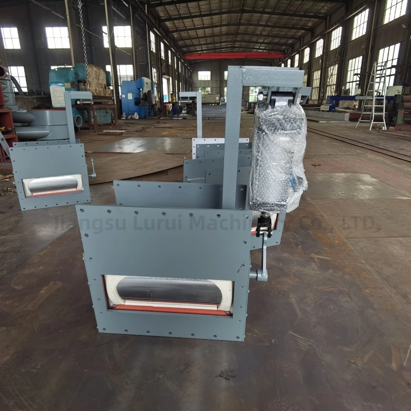
Technical Parameters (Reference)
| Parameter | Specification |
|---|---|
| Material | Carbon Steel |
| Drive Type | Pneumatic |
| Sealing Type | Wool felt / Metal Sealing |
| Operating Pressure | 0.4 – 0.6 MPa |
| Temperature Range | -20℃ to +180℃ |
| Application Material | Cement, Fly Ash, Limestone Powder |
| Installation Position | Under Silo / Hopper / Bin |
*Custom sizes available (800×800 / 1000×1000 / OEM)
How to Select a Pneumatic Flow Control Gate
| Selection Item | What to Confirm |
|---|---|
| Material | Cement, fly ash, lime powder, limestone powder |
| Inlet size | Silo outlet or hopper discharge size |
| Required capacity | Tons per hour or flow rate |
| Air pressure | Usually 0.4–0.6 MPa |
| Control method | Open/close control, limit switch, PLC signal |
| Sealing requirement | Dust sealing or ordinary shut-off |
| Installation position | Under silo, hopper, air slide inlet or screw conveyor inlet |
| Custom requirement | Flange size, material thickness, actuator position |
Advantages
✅ Accurate flow control for cement and bulk powders
✅ Fast response speed for automated processes
✅ Strong structure, vibration-resistant
✅ Stable sealing performance for dust control
✅ Suitable for continuous industrial operation
✅ Available in custom sizes for specific applications
Why Choose LVRUI Pneumatic Flow Control Gate?
✅ Professional manufacturer for bulk material handling equipment
✅ Customized solutions for various industries
✅ High-quality raw materials and precision manufacturing
✅ Stable performance in harsh industrial environments
✅ Competitive price with reliable after-sales support
FAQs About Pneumatic Flow Control Gate
What is a pneumatic flow control gate in bulk material handling?
It is a pneumatically actuated discharge valve used to regulate the flow of dry bulk materials from silos, hoppers, or bins while maintaining effective dust sealing, consistent flow, and system stability.
Where are pneumatic discharge control gates typically installed?
These valves are most often installed beneath storage silos, feeding points, or intermediate bins in cement plants, fly ash systems, and mineral powder processing lines to ensure accurate and stable material handling.
How is a pneumatic flow control gate different from a manual slide gate?
Pneumatic flow control gates provide faster response, automated operation, and more consistent discharge control compared with manually operated slide gates, making them suitable for continuous and automated industrial systems.
What customization options are available for pneumatic flow control gates in industrial applications?
These valves can be customized in discharge size, sealing structure, actuator type, and material thickness to match silo outlet dimensions, material flow characteristics, and operating conditions. Custom configurations help ensure reliable sealing, stable discharge control, and long-term performance in cement silos, fly ash systems, and other bulk material handling environments.
How does a pneumatic flow control gate improve powder handling efficiency?
By providing precise regulation and fast response, pneumatic flow control gates reduce downtime, prevent material bridging, and maintain consistent flow, improving overall efficiency in industrial powder handling systems.
Can pneumatic flow control gates be integrated with other automated systems in cement plants?
Yes. These valves can be seamlessly integrated with conveyors, feeders, loading chutes, and dust collection systems to achieve safe, efficient, and dust-controlled bulk material handling, enabling automated and continuous plant operations.
What air pressure is required for a pneumatic flow control gate?
Most pneumatic flow control gates work with compressed air around 0.4–0.6 MPa, but the final requirement depends on valve size, cylinder type, material condition and control system design.
What is the difference between a pneumatic flow control gate and a motorized flow control gate?
A pneumatic flow control gate is better for fast open/close operation and frequent switching, while a motorized flow control gate is more suitable when precise opening position or adjustable flow control is required.
Ready to Get a Reliable Pneumatic Flow Control Gate Solution?
Partner with LVRUI for professional bulk material handling solutions and responsive technical support.
✅ Get expert quotation and customized solution within 12 hours.
✅ Factory direct supply with strict quality control
✅ Professional engineering support from experienced team
✅ Stable delivery for overseas industrial projects