
Flow Control System for Cement Silos & Bulk Powder Handling
Isolation, Regulation and Routing for Dry Bulk Powder Discharge
What Is a Flow Control System?
A Flow Control System coordinates the devices used to start, stop, regulate or redirect dry bulk material between a silo or hopper and downstream equipment. Depending on the process layout, the system may include shut-off valves, flow control gates, pneumatic or motorized actuators, diverter valves and position-feedback devices.
Its primary purpose is to control when material is discharged, how the discharge opening is adjusted and which downstream route receives the material. Typical applications include cement, fly ash, raw meal, lime powder and other compatible dry bulk powders.
A Flow Control System controls material discharge and routing; it does not convey material by itself or provide precision mass-flow measurement unless separate conveying, weighing or metering equipment is included.
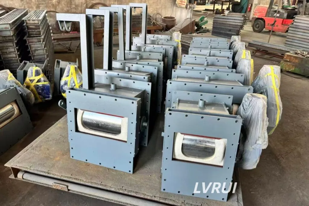
Four Functions of a Flow Control System
1. Material Isolation
A shut-off valve provides full-open or full-close isolation when material flow must be stopped during startup, shutdown, equipment changeover or maintenance. It is normally selected where reliable on/off control is required rather than continuous opening adjustment.
2. Adjustable Discharge
A flow control gate changes the effective discharge opening between a silo or hopper and downstream equipment. This allows material feeding to be adjusted according to downstream capacity or process demand without treating the valve as a precision weighing device.
3. Material Routing
Where one source feeds multiple downstream lines, a diverter valve or air slide diverter can direct material to the selected route. Routing equipment is configured according to the number of outlets, conveying arrangement and operating sequence.
4. Position Feedback and Interlocking
Pneumatic or motorized actuators can be combined with limit switches, position feedback or suitable control interfaces. These signals allow the operating status of the valve or gate to be coordinated with downstream equipment and plant control logic.
Typical Flow Control System Configurations
Single Silo to One Downstream Line
Silo → Shut-Off Valve → Flow Control Gate → Downstream Equipment
This arrangement is used where one silo feeds a single air slide conveyor, screw conveyor, feeder or other downstream process. The shut-off device provides isolation, while the flow control gate adjusts the discharge opening.
Single Silo to Multiple Routes
Silo → Flow Control Gate → Diverter → Line A / Line B
This configuration is suitable when material from one storage source must be directed to alternative conveying lines, storage points or loading routes. The diverter determines the destination while the upstream gate controls material release.
Automated Downstream Feeding
Silo → Isolation Device → Pneumatic or Motorized Flow Control Gate → Process Equipment
Where remote operation is required, actuator status and gate-position signals can be coordinated with downstream equipment. The system can be configured so that material is released only when the receiving equipment is ready.
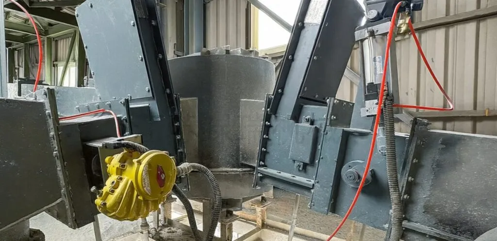
System Configuration Options
✓ Isolation Control — Full-open/full-close shut-off devices can be included where positive material isolation is required.
✓ Adjustable Flow Control — Manual, pneumatic or motorized flow control gates can be selected according to operating frequency and control requirements.
✓ Single or Multiple Material Routes — Diverter equipment can be added where one source must feed more than one downstream line.
✓ Position and Status Feedback — Limit switches, position indication or suitable signal interfaces can be configured when remote status monitoring is required.
✓ Customized Connections — Valve size, flange dimensions and actuator arrangement can be matched to confirmed silo outlets and downstream equipment.
✓ Optional Upstream Lump Breaking — Where hardened powder lumps may interfere with gate operation, a lump breaker can be evaluated before the flow control equipment.
How Does a Flow Control System Work?
A Flow Control System works by coordinating the operating sequence of isolation, regulating and routing devices rather than by conveying the material itself.
Step 1 — Downstream equipment becomes ready.
The receiving conveyor, feeder, loading equipment or process unit is prepared before material discharge begins.
Step 2 — The isolation device opens.
A shut-off valve or gate opens the material passage where separate isolation is required.
Step 3 — The flow control gate moves to the required opening.
The effective discharge area is adjusted according to the required feeding condition and downstream equipment capacity.
Step 4 — Material enters the downstream equipment.
Gravity or the connected conveying equipment moves the discharged powder away from the control point.
Step 5 — The material route is selected where required.
If multiple downstream lines are available, a diverter directs material to the selected destination.
Step 6 — Operating status is confirmed.
Limit switches, position feedback or other control signals can confirm that the relevant gate or valve has reached the required operating position.
During shutdown or an interlock condition, the regulating and isolation devices can be returned to their closed positions according to the required operating sequence.
Select the Control Device by Function
| Operating Requirement | Typical Device | Main Function |
|---|---|---|
| Completely stop material flow | Shut-Off Valve / Slide Gate | Isolation |
| Adjust the discharge opening | Flow Control Gate | Regulation |
| Switch material between routes | Diverter Valve | Routing |
| Fast and frequent remote operation | Pneumatic Actuation | Automated operation |
| Electric operation without compressed air | Motorized Actuation | Adjustable electric control |
| Hardened lumps before the valve | Lump Breaker | Break lumps before flow control |
| Precise mass dosing | Weighing or metering equipment | Measure actual material quantity |
The final configuration should be selected according to the required function rather than using one valve type for every material-handling problem.
Flow Control System vs Other Material Handling Systems
| System | Main Purpose | Primary Function |
|---|---|---|
| Flow Control System | Control material movement | Isolation, regulation and routing |
| Cement Silo Discharge System | Improve reliable discharge from storage | Flow assistance and silo discharge |
| Powder Transfer System | Move material between process points | Conveying |
| Dust Control System | Capture airborne dust | Extraction and filtration |
For a broader overview of conveying, silo discharge, loading and dust-control systems, see our Cement Bulk Material Handling Solutions.
Where Does a Flow Control System Fit in the Process Line?
Typical control points include:
✓ Silo outlet → air slide conveyor
✓ Hopper outlet → screw conveyor or feeder
✓ Storage silo → multiple conveying routes
✓ Intermediate bin → downstream process equipment
✓ Powder conveying line → bulk loading equipment
✓ Silo discharge line → weighing or batching equipment
The Flow Control System is normally positioned at a material discharge or distribution point where isolation, adjustable feeding or route selection is required.
Information Required for Flow Control System Selection
Please provide:
✓ Material and bulk density
✓ Required capacity
✓ Silo or hopper outlet dimensions
✓ Downstream equipment
✓ Required function: isolation, regulation or routing
✓ Number of discharge routes
✓ Available compressed air or electrical power
✓ Control requirements and installation layout
Based on these data, LVRUI can determine the suitable control devices, actuator configuration, routing arrangement and connection dimensions.
Material flow behavior can vary with bulk density, cohesion and other bulk-solid properties. For general reference, ASTM provides guidance on evaluating bulk solids flow properties using shear testing.
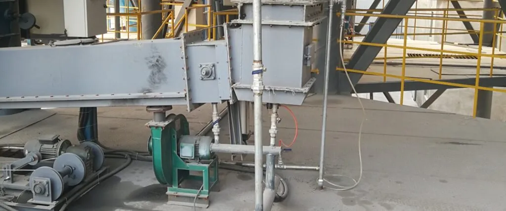
Flow Control System FAQs
What is a Flow Control System used for in bulk powder handling?
A Flow Control System is used to start or stop material discharge, adjust the effective discharge opening and direct material to the required downstream route. It is typically installed between silos or hoppers and conveying, feeding, weighing or loading equipment.
What is the difference between a Flow Control System and a Powder Transfer System?
A Flow Control System controls when material is released, how the discharge opening is adjusted and where the material is directed. A Powder Transfer System physically conveys material between process points using equipment such as air slide conveyors, screw conveyors or other conveying machines.
What is the difference between a shut-off valve and a flow control gate?
A shut-off valve is mainly used for full-open or full-close material isolation. A flow control gate changes the effective opening area to provide adjustable material feeding. Both devices may be used in the same system when separate isolation and flow regulation are required.
Can a Flow Control System provide precise dosing?
Not by itself. A flow control gate adjusts the discharge opening but does not directly measure material mass flow. Applications requiring precise dosing normally need separate weighing, metering or feeding equipment.
Does a Flow Control System prevent silo blockage?
A Flow Control System can help avoid sudden downstream surges and provide controlled discharge, but silo blockage also depends on material flowability, caking, silo geometry and aeration conditions. Aeration equipment or a lump breaker may be required where poor material flow or hardened lumps are present.
What information is required to configure a Flow Control System?
Typical selection data include the material, bulk density, required capacity, silo or hopper outlet dimensions, downstream equipment, required control function, number of material routes, available utilities and control-signal requirements. Installation drawings are also useful when connection dimensions must be confirmed.
Discuss Your Flow Control System Requirements
Send LVRUI your material properties, silo or hopper outlet dimensions, downstream equipment, required control functions and installation layout. LVRUI can recommend the suitable isolation, flow regulation and routing configuration.
✓ Shut-off and flow control device selection
✓ Pneumatic or motorized actuator configuration
✓ Single-line or multi-route arrangement
✓ Technical drawings and remote technical support