Why Small Design Errors Can Lead to Arching, Rat-Holing, Dust Leakage and Conveyor Problems
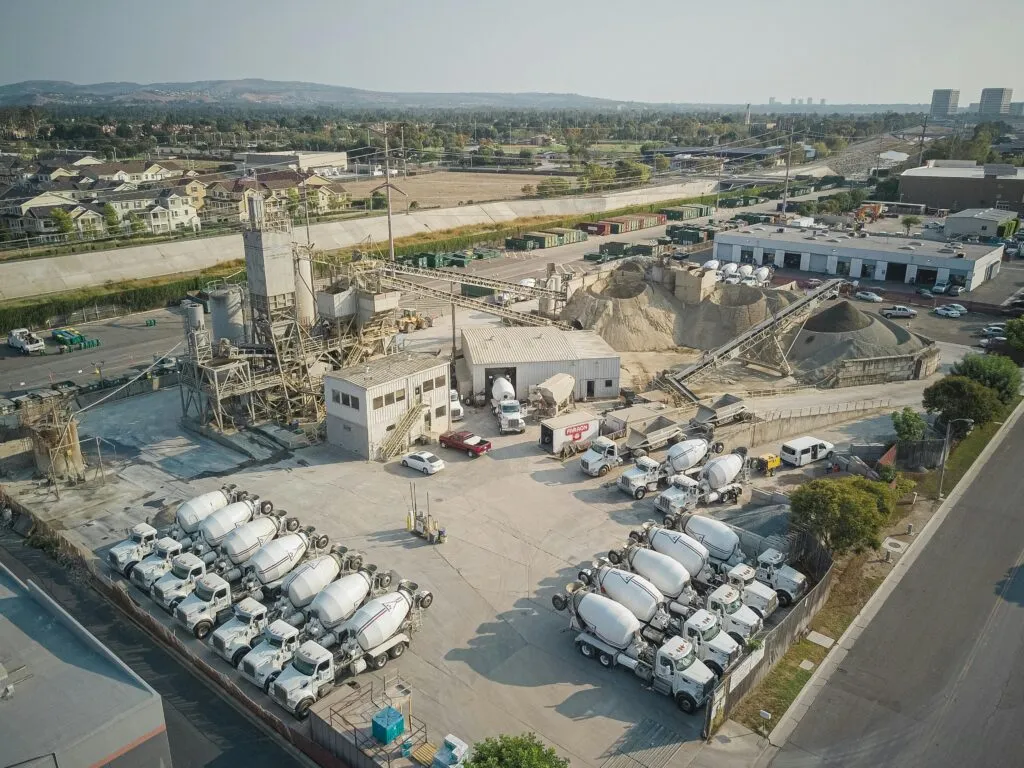
Why Cement Silo Discharge Design Matters
A good cement silo discharge design should make cement powder leave the silo in a stable, controlled and dust-contained way before it enters downstream conveying or loading equipment.
In many cement plants, the discharge problem is not caused by one single machine. Operators may see blockage at the screw conveyor, unstable flow in the air slide conveyor, leakage around the flow control gate or dust around the loading point. But the real cause may be poor system matching at the silo bottom.
Cement powder is a fine bulk material. It can become compacted, form dead zones, bridge above the outlet, leak dust from poor connections, or overload downstream equipment if the discharge system is not designed correctly.
That is why cement silo discharge design should be considered as a complete system, not just a valve, chute or conveyor.
Mistake 1: Treating Silo Discharge as a Single Device
One common mistake is treating silo discharge as only one piece of equipment.
Some plants focus only on the discharge valve. Others focus only on the conveyor below the silo. But stable cement discharge depends on several parts working together.
A complete silo bottom discharge arrangement may include:
√ Silo outlet structure
√ Aeration pads or aeration boxes
√ Air supply and air distribution system
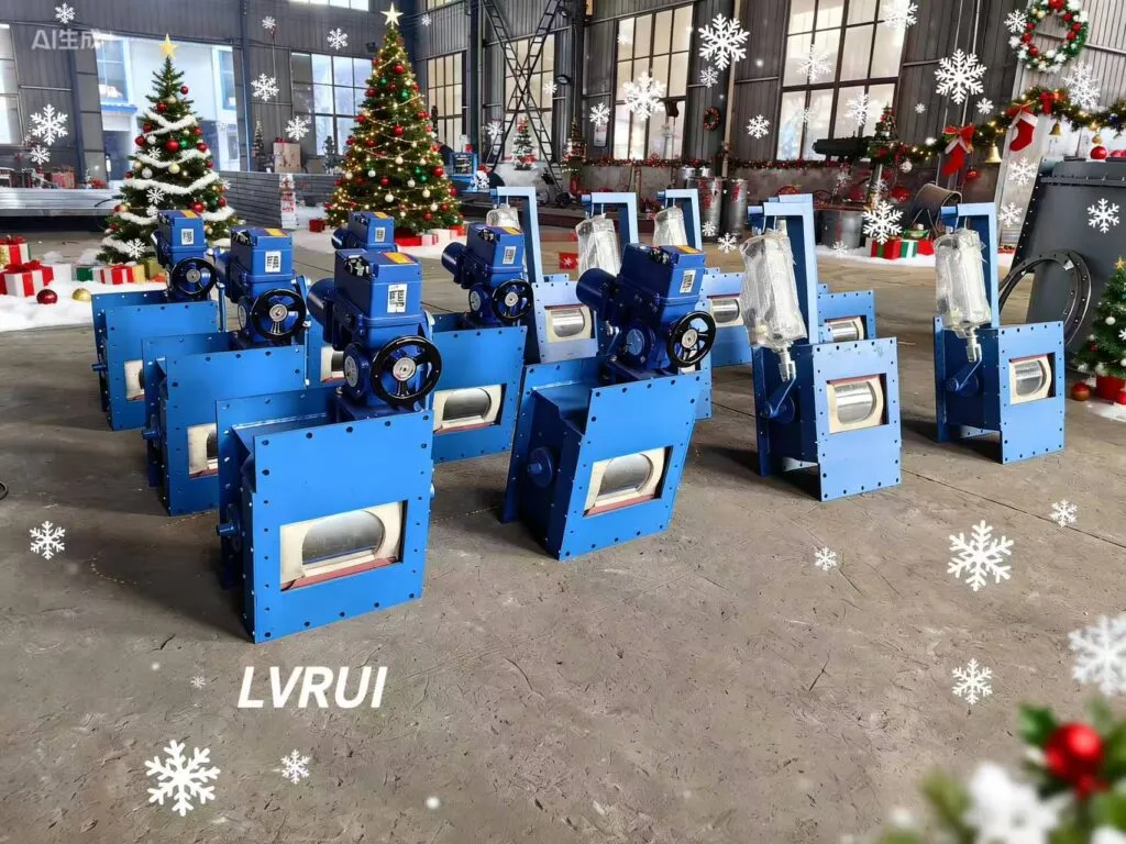
√ Flow control gate
√ Slide gate valve
√ Rotary valve
√ Screw conveyor
√ Air slide conveyor
√ Dust collection connection
√ Maintenance platform and inspection access
√ Control and interlock system
If one part is selected without considering the others, the system may still fail. For example, a large silo outlet does not help if the downstream conveyor has insufficient capacity. A good flow control gate cannot stabilize discharge if the powder is poorly aerated. A strong conveyor cannot solve the problem if hardened cement lumps enter the inlet.
A reliable cement silo discharge design should start from the whole discharge path: from the silo cone to the final downstream conveyor or loading equipment.
This is why cement silo discharge design should be reviewed as one complete material flow path, not as separate equipment.
Mistake 2: Poor Aeration Pad Layout
Cement powder usually needs proper aeration to discharge smoothly from the silo bottom. If aeration is uneven, the powder may flow in some areas while remaining compacted in others.
Poor aeration layout may cause:
√ Arching above the silo outlet
√ Rat-holing inside the silo
√ Dead material zones
√ Unstable discharge rate
√ Sudden material collapse
√ Local compaction near the outlet
√ Frequent manual cleaning
√ Poor flow after long storage
Aeration pads should not be placed randomly. Their position, quantity, air pressure and air distribution should match the silo cone, material condition and discharge requirement.
If aeration is too weak, the powder may not fluidize properly. If aeration is uneven, the material may flow only through limited paths. If air pressure is too high or poorly controlled, it may create local disturbance instead of stable flow.
For cement plants, aeration should be checked together with the silo outlet structure and discharge equipment. A flow problem at the bottom is often a sign of poor air distribution inside the discharge zone.
Mistake 3: Choosing the Wrong Flow Control Gate
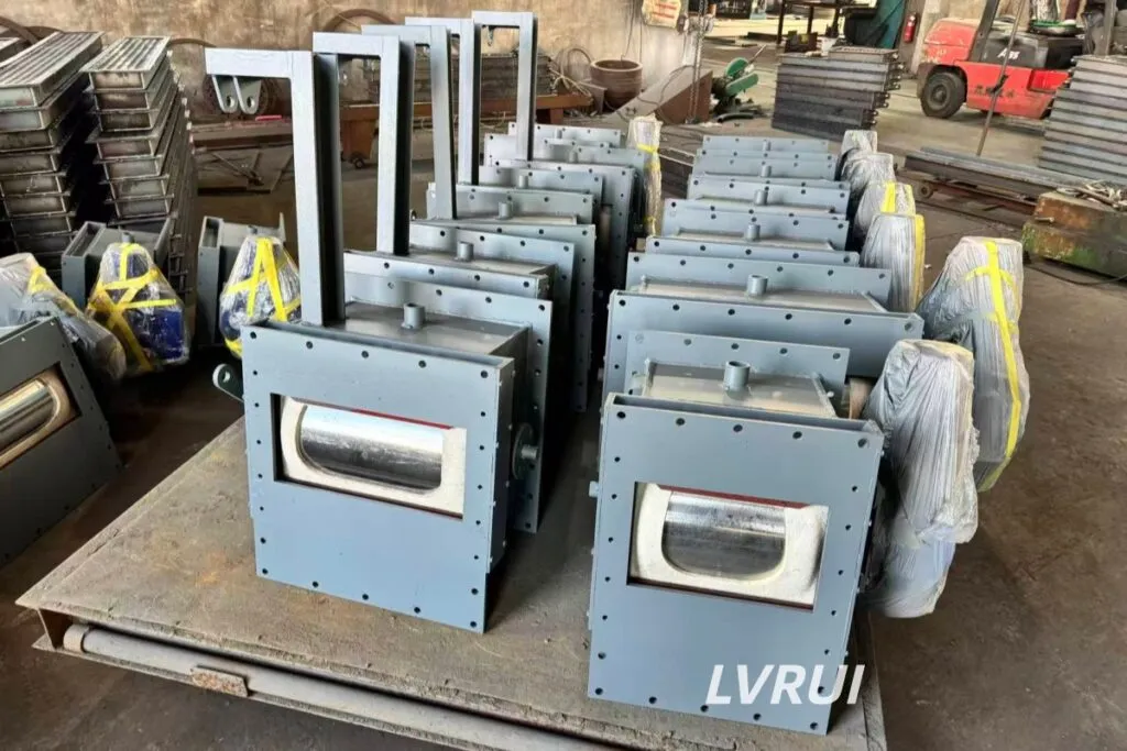
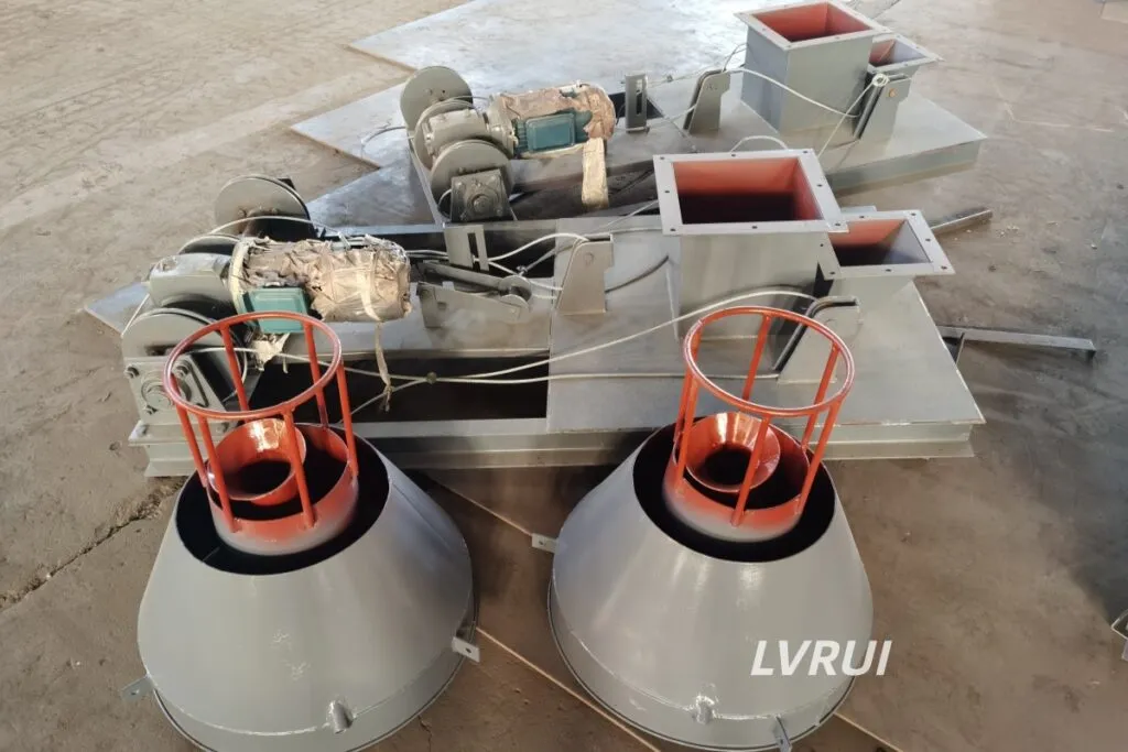
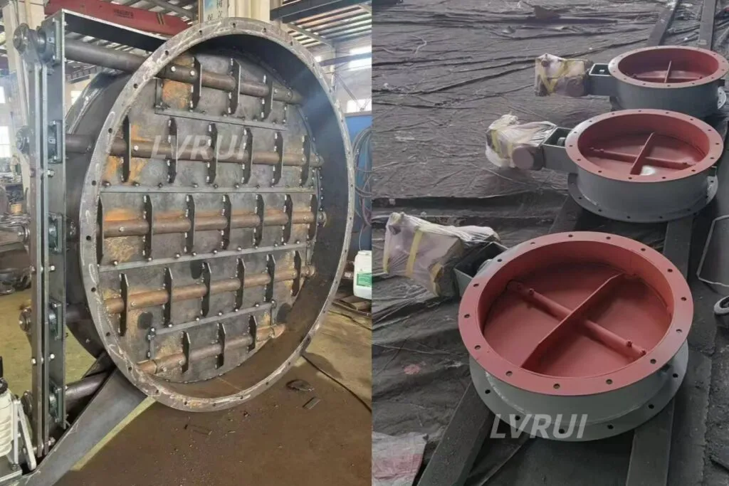
A flow control gate is used to regulate cement powder discharge from the silo, hopper or conveying system. It should help operators control flow rate smoothly and prevent sudden material surges.
But the gate itself cannot solve every discharge problem.
Wrong gate selection may cause:
√ Poor flow adjustment
√ Sudden discharge surge
√ Material leakage
√ Gate plate wear
√ Poor sealing
√ Actuator overload
√ Material trapped near the gate opening
√ Downstream conveyor overload
A flow control gate must match the required capacity, outlet size, material condition and control method. If the gate is too small, it may restrict flow. If it is too large, the downstream system may receive too much material at once. If cement lumps or compacted material reach the gate, the gate may fail to close fully.
The gate should be selected as part of the cement silo discharge design, not as a separate accessory. Its opening range, sealing method, drive type and connection with downstream equipment should all be considered.
Mistake 4: Ignoring Downstream Conveyor Capacity
A silo may be able to discharge more material than the downstream equipment can handle. This is a common reason for blockage and unstable flow.
If the discharge rate is higher than conveyor capacity, the system may face:
√ Screw conveyor inlet blockage
√ Air slide conveyor overload
√ Material buildup at transfer points
√ Unstable loading flow
√ Increased dust release
√ Motor overload
√ Emergency shutdown
√ Frequent cleaning around the conveyor inlet
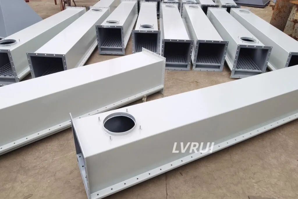
The downstream equipment determines how much material can be safely accepted. A screw conveyor has a limited inlet size and conveying capacity. An air slide conveyor depends on stable fluidization and proper material depth. A loading spout requires stable feeding to keep loading smooth.
If the flow control gate discharges too fast, even a well-designed conveyor may become overloaded. Therefore, cement silo discharge design must match the silo outlet, gate opening and conveyor capacity together. A stable cement silo discharge design must match the actual capacity of the downstream conveyor.
Mistake 5: No Protection Against Cement Lumps
Cement powder can form hardened lumps because of moisture, compaction, long storage time or unstable silo conditions. If these lumps enter downstream equipment, they may block conveyors, jam valves or interrupt loading.
Cement lumps may affect:
√ Flow control gates
√ Slide gate valves
√ Rotary valves
√ Screw conveyors
√ Air slide conveyors
√ Loading spouts
√ Cement bulk loaders
√ Transfer chutes
A flow control gate is designed to regulate powder flow, not to crush hard blocks. A screw conveyor is designed to convey powder, not to receive oversized cement lumps. An air slide conveyor needs fine, flowable powder for stable fluidization.
If hardened lumps repeatedly appear at the silo outlet, upstream lump control should be considered before the material enters sensitive downstream equipment.
The key is to identify whether the problem is only poor flow, or whether oversized hardened material is already entering the discharge line.
Mistake 6: Poor Dust Sealing at Discharge Interfaces
Dust leakage is not only a housekeeping issue. It often shows that the discharge interface is not properly sealed or matched.
Common leakage points include:
√ Silo outlet flange
√ Gate connection
√ Conveyor inlet
√ Rotary valve connection
√ Loading chute
√ Inspection door
√ Transfer point
√ Bulk loading interface
Poor dust sealing may cause:
√ Dust around the silo bottom
√ Material loss
√ Poor working environment
√ Extra cleaning work
√ Air leakage affecting conveying performance
√ Faster wear around connection points
√ Reduced dust collection efficiency
In cement silo discharge design, sealing should be considered at every transition point. Even if the bag filter or dust collector works well, dust may still escape if the flange, chute or conveyor inlet is poorly connected.
A dust collection system should not be treated as a backup for bad mechanical sealing. The first step is to reduce leakage at the source.
Dust leakage is often a sign that the cement silo discharge design does not properly match the mechanical sealing and dust collection points.
Mistake 7: No Maintenance Access Around Silo Bottom Equipment
Many discharge problems become worse because maintenance is difficult.
If operators cannot easily inspect the silo outlet, gate, aeration pipe, conveyor inlet or dust connection, small issues may not be found until they become serious.
Poor maintenance access may lead to:
√ Slow blockage removal
√ Long downtime
√ Missed early warning signs
√ Difficult valve inspection
√ Poor aeration maintenance
√ Unsafe manual cleaning
√ Delayed filter or dust duct inspection
√ Repeated emergency repair
A practical cement silo discharge design should leave enough space for inspection and service. Maintenance access should be considered during the layout stage, not after installation.
Important maintenance points include:
√ Inspection doors near the discharge point
√ Space for gate actuator maintenance
√ Access to aeration air lines
√ Space around screw conveyor inlet
√ Access to rotary valve or air slide inlet
√ Safe platform around silo bottom equipment
√ Convenient dust duct inspection
√ Clear cleaning points at transition areas
If operators need to disassemble too many parts just to clean a blockage, the discharge system is already difficult to maintain.
Mistake 8: Weak Control Logic Between Gate and Conveyor
Mechanical design is only one part of a stable discharge system. Control logic also matters.
If the discharge gate opens before the conveyor starts, material may accumulate at the inlet. If the conveyor stops but the gate remains open, material may flood the downstream equipment. If the aeration system does not start before discharge, powder may not flow properly.
Weak control logic may cause:
√ Sudden material surge
√ Conveyor overload
√ Unstable start-up
√ Material buildup after shutdown
√ Poor flow adjustment
√ Emergency stop problems
√ Unsafe manual operation
A better control sequence should consider:
√ Aeration start-up before discharge
√ Conveyor running confirmation
√ Gate opening control
√ Flow adjustment according to downstream capacity
√ Interlock between valve and conveyor
√ Emergency stop logic
√ Delayed shutdown for material clearing
For cement plants, the goal is not only to open and close equipment. The goal is to make material flow start, run and stop in a controlled way.
Cement Silo Discharge Design Checklist
The following checklist can help identify weak points in a cement silo discharge system.
| Design Point | What to Check | Risk if Ignored |
|---|---|---|
| Aeration layout | Coverage, air pressure, airflow balance | Arching, rat-holing, unstable discharge |
| Silo outlet | Outlet size, cone structure, material flow path | Bridging and poor powder flow |
| Flow control gate | Size, sealing, drive type, control mode | Sudden surge, leakage, poor regulation |
| Downstream conveyor | Capacity, inlet size, conveying method | Conveyor overload or blockage |
| Lump risk | Storage time, moisture, lump size | Valve jamming and conveyor blockage |
| Dust sealing | Flange, chute and conveyor connection | Dust leakage around discharge points |
| Maintenance access | Inspection doors, service space, platform | Difficult cleaning and long downtime |
| Control logic | Interlock between aeration, gate and conveyor | Unsafe or unstable discharge |
| Loading connection | Feed stability before loading spout or bulk loader | Unstable loading and dust generation |
| Dust collection | Dust source, duct connection, filter capacity | Poor dust control around silo bottom |
This checklist is useful because many cement silo discharge problems are caused by several small issues at the same time. A blocked conveyor may not be only a conveyor problem. It may come from poor aeration, wrong gate opening, oversized lumps or mismatched discharge capacity.
For general conveyor selection and bulk material handling background, the conveyor equipment engineering reference from CEMA can be used as an industry reference when checking downstream conveyor capacity and system matching.
How to Diagnose Poor Cement Silo Discharge
Before replacing equipment, the plant should first identify where the problem starts.
Useful diagnosis questions include:
√ Does the problem happen after long storage?
√ Does it become worse in humid weather?
√ Is the silo aeration working evenly?
√ Is the material compacted near the outlet?
√ Does the flow control gate open and close smoothly?
√ Is the downstream conveyor overloaded?
√ Are hardened cement lumps found during cleaning?
√ Is dust leaking from the flange or chute connection?
√ Does blockage happen at the same point repeatedly?
√ Does the system stop during start-up or shutdown?
If the problem appears only at the conveyor inlet, the conveyor may not be the root cause. If dust escapes around the gate, the issue may be poor sealing or excessive material surge. If blockage happens after long shutdowns, moisture and compaction should be checked first.
A practical diagnosis should follow the material path from silo outlet to downstream equipment.
How to Improve Cement Silo Discharge Design
Improving silo discharge performance does not always mean replacing the whole system. In many cases, small but correct adjustments can make the system more stable.
Possible improvements include:
√ Adjust aeration pad layout
√ Check air pressure and airflow balance
√ Improve silo outlet sealing
√ Select a suitable flow control gate
√ Match gate opening with conveyor capacity
√ Add upstream lump control if hardened lumps appear
√ Improve dust sealing at connection points
√ Add inspection doors and maintenance access
√ Improve interlock control between gate and conveyor
√ Check dust collection duct connection
√ Reduce long-term dead storage where possible
For a new project, these points should be considered before equipment manufacturing. For an existing plant, the first step is to locate the weakest point in the discharge path.
FAQ About Cement Silo Discharge Design
What causes poor cement silo discharge?
Poor cement silo discharge is often caused by uneven aeration, material compaction, incorrect flow control gate selection, poor silo outlet design, downstream conveyor mismatch or cement lumps near the discharge point. A good cement silo discharge design should control powder flow, reduce blockage risk and protect downstream conveying equipment.
Why does cement powder bridge near the silo outlet?
Cement powder may bridge when it becomes compacted, poorly aerated or affected by moisture. If the silo outlet geometry and aeration layout are not suitable, powder may form an arch above the discharge point.
Can aeration solve all cement silo discharge problems?
No. Aeration can improve powder flow, but it cannot solve every problem. If the flow control gate is wrongly selected, the downstream conveyor is overloaded, or hardened lumps already exist, additional system adjustments may be needed.
Why does a flow control gate fail to stabilize discharge?
A flow control gate may fail if the gate size is wrong, material flow is uneven, cement lumps are trapped near the gate plate, or the downstream conveyor cannot accept the discharge rate.
What happens if the silo discharge rate is higher than conveyor capacity?
The downstream conveyor may overload, block at the inlet or cause material buildup. In severe cases, the conveyor, valve or loading system may stop unexpectedly.
When should a cement plant consider upstream lump control?
Upstream lump control should be considered when hardened cement lumps repeatedly reach valves, screw conveyors, air slide conveyors or bulk loading systems and cause blockage or unstable discharge.
How can dust leakage around silo discharge points be reduced?
Dust leakage can be reduced by improving flange sealing, using dust-tight discharge interfaces, matching the valve and conveyor connection, and adding suitable dust collection equipment at high-dust points.
Why is maintenance access important in silo discharge design?
Maintenance access is important because silo bottom equipment may need inspection, cleaning and adjustment. Without enough access space, small problems may become long shutdowns.
What information is needed before redesigning a silo discharge system?
Important information includes silo size, outlet size, material type, moisture condition, discharge capacity, aeration layout, downstream equipment, blockage position, dust leakage points and available installation space.
Is poor cement silo discharge always caused by the silo itself?
No. The problem may also come from the flow control gate, conveyor inlet, dust sealing, aeration system, control logic or downstream equipment mismatch. The whole discharge path should be checked.
Contact LVRUI for Cement Silo Discharge Design Support
If your cement plant has unstable silo discharge, arching, rat-holing, dust leakage, conveyor blockage or repeated manual cleaning, the problem should be checked from the silo outlet to the downstream conveying or loading equipment.
Jiangsu Lvrui Machinery Co., Ltd. provides dry bulk material handling equipment for cement plants, grinding stations, fly ash systems, lime powder systems and mineral powder production lines. We can help select suitable equipment for silo discharge, powder conveying, flow control, dust collection and bulk loading systems.
For a proper recommendation, please provide the following information:
√ Material name
√ Silo outlet size
√ Silo bottom layout
√ Discharge capacity
√ Aeration arrangement
√ Downstream equipment
√ Blockage position
√ Dust leakage point
√ Installation space
√ Photos or drawings of the current discharge system
Contact LVRUI for a customized cement silo discharge solution:
WhatsApp: +86-18261998937
WeChat: +86-18261998937
Email: info@lvrui-conveyor.com
Simplified Indonesian Version
Desain discharge silo semen yang kurang tepat dapat menyebabkan aliran bubuk tidak stabil, bridging, rat-holing, kebocoran debu, overload conveyor, dan penyumbatan pada valve. Masalah ini tidak selalu berasal dari satu alat saja, tetapi sering terjadi karena aerasi tidak merata, pemilihan flow control gate yang tidak sesuai, kapasitas conveyor tidak cocok, atau adanya gumpalan semen di area outlet silo.
Untuk meningkatkan kinerja discharge, pabrik semen perlu memeriksa layout aerasi, ukuran outlet, koneksi valve, kapasitas downstream conveyor, sealing debu, akses maintenance, dan sistem interlock. Jika masalah sering berulang, seluruh jalur material dari silo outlet sampai conveyor atau loading system harus diperiksa secara sistematis.