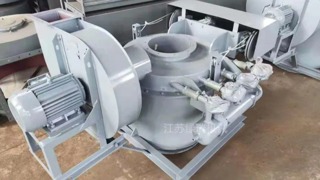
Engineering guide for preventing tanker overflow, dust leakage, and delayed shut-off in bulk cement loading systems
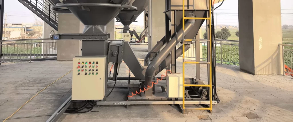
Cement tanker overfill protection is a common problem in bulk cement loading systems. During cement, fly ash, lime powder, mineral powder, or dry mortar loading, the operator cannot directly see the material level inside the tanker. If the system does not detect full level in time, powder may overflow from the tanker inlet, create heavy dust, contaminate the loading area, and cause material loss.
In many cement plants and grinding stations, overfill does not happen because of one single equipment failure. It is often caused by a combination of fast material flow, delayed valve closing, poor level detection, weak control logic, and improper loading spout positioning.
A reliable bulk loading system should not only load fast. It should also stop at the right time. For this type of dry powder application, a dry powder level switch for cement tanker loading can send a full-level signal before overflow becomes serious.
What Causes Cement Tanker Overfill During Bulk Loading?
Cement tanker overfill usually happens near the end of loading. At the beginning, the material flows smoothly into the tanker. As the tanker becomes full, the remaining air inside the tank is displaced, powder rises near the inlet, and dust pressure increases around the loading head.
If the system cannot detect this condition quickly, overfill may happen.
Common causes include:
√ Manual judgment is too slow
√ The operator cannot see the material level inside the tanker
√ The loading rate is too high near the final stage
√ The flow control gate closes too late
√ The level detection device is not suitable for dry powder
√ The loading spout is not inserted or positioned correctly
√ The control system does not stop feeding immediately
√ Dust extraction is weak near the tanker inlet
√ The tanker inlet and loading head are not properly sealed
For fine powder such as cement and fly ash, even a short delay can cause visible overflow and dust leakage. This is why cement tanker overfill protection should be considered as a complete system design, not only a sensor selection issue.
Why Cement Powder Is Difficult to Detect During Tanker Loading
Cement powder is not a liquid. This point is important.
Liquid level detection methods are not always suitable for cement tanker loading because dry powder behaves differently. Cement, fly ash, lime powder, and mineral powder may flow, fluidize, compact, bridge, or generate dust depending on air pressure and material condition.
During tanker loading, the material surface is not always flat. Powder may rise unevenly near the loading inlet. Dust and air movement can also affect the detection result.
A reliable full-level detection method for cement tanker loading should consider:
√ Dry powder behavior
√ Dust concentration
√ Air displacement inside the tanker
√ Loading spout position
√ Material flow speed
√ Signal response time
√ Control cabinet logic
√ Valve closing delay
For cement tanker overfill protection, the detection system must respond quickly enough to stop feeding before powder escapes from the tanker inlet.
7 Practical Ways to Improve Cement Tanker Overfill Protection
1. Use a Dry Powder Full-Level Detection Method
The first step is choosing a detection method suitable for dry powder, not liquid. In cement tanker loading, the device should detect when powder reaches the target level near the loading head and then send a signal to the control system.
An air pressure solids level switch can be used for this type of application. The working principle is different from a liquid level sensor. It uses air pressure change to detect whether dry powder blocks the sensing point. When cement powder reaches the detection position, the pressure condition changes, and the switch signal can be used to stop loading.
This type of dry powder detection is especially useful when the sensor needs to work with a loading spout, tanker loading system, or dry ash bulk loader.
2. Install the Detection Point Near the Loading Head
The detection point should be close to the real full-level position. If it is too far from the loading head, the system may detect too early or too late.
For cement tanker overfill protection, the detection point is often arranged near the lower part of the loading spout or around the area where powder rises during final filling. This helps the system react when the tanker is almost full.
The installation should consider:
√ Tanker inlet height
√ Loading spout insertion depth
√ Powder rising position
√ Blow pipe or sensing pipe location
√ Dust extraction direction
√ Whether the sensing point is protected from damage
A poorly positioned sensor may create false signals or fail to stop loading in time.
3. Connect the Switch Signal to the Loading Control System
Detection alone is not enough. The full-level signal must be connected to the loading control system and trigger the correct action.
A practical control logic may include:
√ Full-level signal received
√ Flow control gate closes
√ Feeding equipment stops
√ Loading spout stops discharging
√ Alarm light or buzzer turns on
√ Operator confirms the loading status
√ System prepares for next loading cycle
For cement tanker overfill protection, the response must be fast and clear. If the signal is only used as a warning but does not stop the loading process, overflow may still happen.
The better solution is to connect the level switch signal with the control cabinet and valve closing logic.
4. Match the Flow Control Gate Response Time
Even if the full-level signal is accurate, material may still continue flowing for a short time after the valve starts closing. This is called delayed shut-off.
A flow control gate or discharge valve must close quickly enough to stop the material before overflow happens. If the gate reacts slowly, the tanker may still receive extra cement after the full-level signal.
For this reason, cement tanker overfill protection should always consider valve response time.
Important points include:
√ Valve opening and closing speed
√ Material flow rate
√ Distance between valve and loading spout
√ Residual material inside the chute
√ Control signal delay
√ Whether slow feeding is needed near the final stage
If the loading rate is high, the system may need a two-stage loading mode: fast loading first, then slower loading near the target level.
5. Reduce Feeding Speed Near the End of Loading
Fast loading improves efficiency, but it increases overfill risk near the final stage. When the tanker is nearly full, the system should avoid sudden high-volume discharge.
A better approach is:
√ Fast feeding during the main loading stage
√ Slow feeding near the final stage
√ Full-level detection before overflow
√ Quick shut-off after signal output
This method reduces the amount of material that continues to fall after the stop signal. It also helps reduce dust pressure near the tanker inlet.
For cement tanker overfill protection, the final stage is usually more important than the beginning stage. Many overflow problems happen in the last few seconds.
6. Keep the Loading Spout Properly Positioned
The loading spout guides cement powder into the tanker and helps control dust around the inlet. If the loading spout is too high, too shallow, or not aligned with the tanker inlet, powder may splash, dust may escape, and full-level detection may become unstable.
A suitable loading spout position helps:
√ Guide powder into the tanker
√ Reduce dust escape
√ Improve full-level detection stability
√ Keep the sensing point in the correct area
√ Reduce overflow risk
√ Improve operator control
The loading head should match the tanker inlet size and working height. For tanker loading, a dust-sealing structure is also important.
7. Check Dust Extraction and Sealing Around the Tanker Inlet
Overflow and dust leakage often appear together. When the tanker is nearly full, air and dust are pushed upward. If dust extraction and sealing are weak, powder may escape even before actual overfill happens.
A dust-controlled loading system should include:
√ Proper sealing around the tanker inlet
√ Dust extraction near the loading head
√ Bag filter or dust collection system
√ Good connection between loading spout and dust collector
√ Regular inspection of sealing parts
√ Stable negative pressure near the loading area
Dust collection cannot replace full-level detection, but it helps control the dust generated during loading. For a cleaner loading system, cement tanker overfill protection and dust control should work together.
For general dust reduction strategy, plant managers may also review industrial dust control guidance when evaluating source capture, ventilation, and engineering controls.
Air Pressure Detection vs Rotary Paddle Level Switch
Different level detection devices are used in different dry powder applications. For cement tanker overfill protection, it is important to choose a device that matches the loading condition.
| Item | Air Pressure Solids Level Switch | Rotary Paddle Level Switch |
|---|---|---|
| Detection principle | Detects air pressure change when powder blocks the sensing point | Detects resistance when material blocks paddle rotation |
| Typical application | Cement tanker loading, dry ash bulk loading, loading spout full-level detection | Silo or hopper point level detection |
| Contact with material | Usually through air pipe or sensing point | Paddle contacts material directly |
| Suitable material | Cement, fly ash, lime powder, dry powder | Powders and granules in silos or hoppers |
| Best use | Fast full-level signal during loading | High or low level detection in storage bins |
| Main advantage | Suitable for dry powder loading spout applications | Simple structure for storage level detection |
A rotary paddle level switch can be useful in silos and hoppers, but tanker loading is a different working condition. During loading, the detection point is close to the loading head, dust is active, and the signal must stop the loading process quickly.
That is why air pressure detection can be a practical choice for dry powder tanker loading systems.
How Overfill Protection Works with Loading Spouts and Flow Control Gates
A reliable system should create a control loop, not only install a sensor.
A typical cement tanker overfill protection process may work like this:
√ Cement powder flows from silo or hopper
√ Flow control gate regulates material discharge
√ Loading spout guides cement into the tanker
√ Air pressure level switch monitors the full-level point
√ When powder reaches the detection point, a switch signal is sent
√ Control cabinet closes the flow control gate
√ Feeding stops before overflow becomes serious
√ Dust collector captures remaining dust near the loading head
This system-level logic is more reliable than manual observation. It also reduces dependence on operator judgment.
For cement plants, fly ash terminals, grinding stations, and dry powder loading sites, overfill protection should be designed together with loading spout, valve, sensor, dust collector, and control cabinet.
Common Mistakes in Cement Tanker Overfill Protection
Mistake 1: Treating Cement Powder Like Liquid
Cement powder does not behave like water. Its surface can be uneven, dusty, compacted, or fluidized. Using the wrong level detection method may cause delayed response or false signals.
Mistake 2: Installing the Detection Point Too High or Too Low
If the detection point is too high, overflow may happen before the signal is triggered. If it is too low, the system may stop loading too early and reduce loading efficiency.
Mistake 3: Ignoring Valve Closing Delay
After the stop signal is sent, some material may still fall into the tanker. If this delay is not considered, overfill can still occur.
Mistake 4: Depending Only on Operator Observation
Manual observation is not reliable when the tanker inlet is covered by the loading head or dust. Operators may not see the real material level inside the tanker.
Mistake 5: Not Checking Dust Extraction
When dust extraction is weak, operators may confuse dust leakage with overfill. Both problems should be checked together.
Mistake 6: Using One Fixed Setting for All Tankers
Different tankers may have different inlet structures, heights, internal volume, and loading behavior. The system should allow proper adjustment for real site conditions.
Buyer Checklist Before Choosing a Cement Tanker Full-Level Detection Device
Before selecting equipment for cement tanker overfill protection, buyers should prepare the following information:
√ Material name: cement, fly ash, lime powder, mineral powder, or dry ash
√ Loading method
√ Loading spout type
√ Tanker inlet size
√ Tanker height
√ Loading capacity
√ Required stop signal type
√ Power supply
√ Control cabinet logic
√ Flow control gate type
√ Valve closing time
√ Dust extraction method
√ Installation position of the sensor box
√ Air pipe size and length
√ Whether site photos or drawings are available
This information helps the supplier check whether the detection device can match the loading system, valve control, and site layout.
Practical System Layout for Cement Tanker Overfill Protection
A practical system layout may include:
√ Cement silo or storage hopper
√ Silo discharge valve
√ Flow control gate
√ Loading spout
√ Air pressure solids level switch
√ Dust collector or bag filter
√ Control cabinet
√ Operator platform
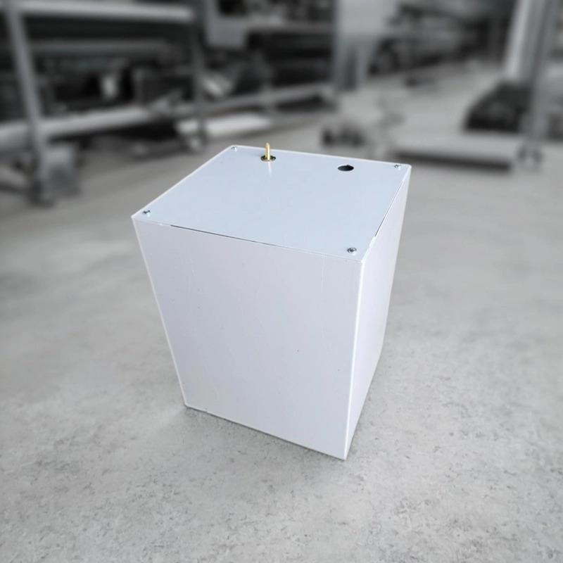
The level switch box can be installed on the bulk loader platform or near the loading control area. The air pipe connects the box with the sensing point near the loading head. When cement powder reaches the sensing point, the pressure change triggers a switch signal.
This signal can be used to close the flow control gate and stop the loading process.
FAQs About Cement Tanker Overfill Protection
What is cement tanker overfill protection?
Cement tanker overfill protection means preventing cement powder, fly ash, lime powder, or other dry bulk material from overflowing during tanker loading. It usually involves dry powder level detection, loading spout positioning, flow control gate shut-off, and control system logic.
Why does cement tanker overfill happen during bulk loading?
Cement tanker overfill happens when the system fails to detect full level in time or does not stop material discharge quickly enough. Common causes include fast loading speed, delayed valve closing, poor level detection, incorrect loading spout position, and weak control logic.
Why is cement powder difficult to detect like a liquid?
Cement powder is a dry bulk solid, not a liquid. It may fluidize, compact, rise unevenly, or generate dust during loading. This makes cement tanker overfill protection different from liquid level detection.
What device can be used for cement tanker full-level detection?
An air pressure solids level switch can be used for cement tanker full-level detection. It detects pressure change when dry powder reaches and blocks the sensing point, then outputs a switch signal to the control system.
How does an air pressure solids level switch prevent tanker overfill?
When cement powder reaches the detection point near the loading head, the air pressure condition changes. The switch sends a signal to the control cabinet, which can close the flow control gate or stop the feeding equipment before serious overflow happens.
Can a rotary paddle level switch be used for cement tanker loading?
A rotary paddle level switch is more commonly used for silo or hopper point level detection. Cement tanker loading requires faster response near the loading head, so air pressure detection may be more suitable for this working condition.
What is the role of a flow control gate in overfill protection?
The flow control gate regulates cement discharge and closes after receiving the stop signal. For cement tanker overfill protection, the gate closing time should be matched with the loading speed and control logic.
Does a loading spout affect overfill protection?
Yes. The loading spout position affects powder flow, dust escape, and full-level detection. If the loading spout is not properly aligned with the tanker inlet, overfill protection may become less stable.
Can dust collection prevent cement tanker overflow?
Dust collection can reduce dust escape, but it cannot replace full-level detection. A dust collector helps control airborne dust, while the overfill protection system stops material discharge when the tanker is full.
What information is needed before choosing a cement tanker overfill protection system?
Useful information includes material type, loading spout structure, tanker inlet size, loading capacity, valve type, control signal requirement, power supply, installation platform, and site photos or drawings.
How can delayed shut-off be reduced during cement tanker loading?
Delayed shut-off can be reduced by using faster valve response, two-stage feeding, proper signal connection, and shorter material path between the flow control gate and loading head. The system should stop material before overflow becomes visible.
Is cement tanker overfill protection necessary for fly ash loading?
Yes. Fly ash is also a fine dry powder and may create dust or overflow during tanker loading. The same design logic can be used for cement, fly ash, lime powder, mineral powder, and other dry bulk materials.
Conclusion
Cement tanker overfill protection is not only a sensor problem. It is a complete loading system issue involving dry powder detection, loading spout position, flow control gate response, dust extraction, and control cabinet logic.
For cement, fly ash, lime powder, and other dry bulk materials, overfill often happens because the system cannot detect full level or stop feeding quickly enough. A practical solution should detect the powder level near the loading head, send a reliable switch signal, close the discharge valve in time, and keep dust under control around the tanker inlet.
When these parts work together, bulk loading becomes cleaner, safer, and more stable.
Contact Jiangsu Lvrui Machinery Co., Ltd.
Jiangsu Lvrui Machinery Co., Ltd. provides air pressure solids level switches, loading spouts, bulk loader systems, flow control gate valves, bag filters, air slide conveyors, and bulk material handling solutions for cement plants, fly ash terminals, grinding stations, and dry powder industries.
If you need cement tanker overfill protection for bulk cement, fly ash, lime powder, or dry powder loading, you can send us your loading spout structure, tanker inlet size, material information, control signal requirement, flow control gate type, plant layout, and site photos. Our team can help check the suitable detection method, installation position, control logic, and system configuration.
For quotation or technical support, please contact us:
WhatsApp: +86-18261998937
WeChat: +86-18261998937
Email: info@lvrui-conveyor.com
Website: lvrui-conveyor.com
Indonesian Short Version
Cement tanker overfill protection digunakan untuk mencegah semen, fly ash, kapur, atau material bubuk kering meluap saat proses bulk loading ke tanker. Masalah overfill biasanya terjadi karena level material tidak terdeteksi tepat waktu, flow control gate terlambat menutup, atau posisi loading spout kurang tepat.
Untuk mencegah overfill, sistem perlu menggunakan metode deteksi level untuk dry powder, bukan liquid level sensor. Air pressure solids level switch dapat mendeteksi perubahan tekanan saat bubuk semen mencapai titik deteksi, lalu mengirim sinyal ke control cabinet untuk menghentikan loading.
Jiangsu Lvrui Machinery Co., Ltd. menyediakan air pressure solids level switch, loading spout, flow control gate, bag filter, dan solusi bulk loading untuk pabrik semen dan fly ash terminal.