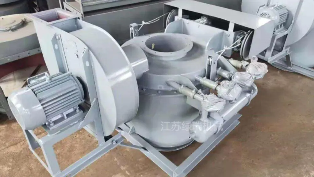
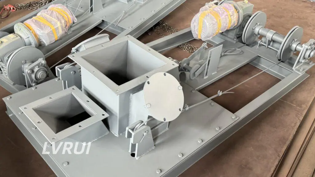
A practical guide to bottom and side discharge layouts for cement, raw meal, fly ash and other dry powder silos.
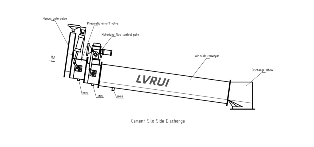
Cement silo bottom and side discharge arrangements connect stored powder with downstream bulk loading equipment and determine how material is isolated, regulated and transferred into a tanker.
For cement, raw meal, fly ash, slag powder, limestone powder and other compatible dry powders, the discharge arrangement may be installed directly beneath the silo or connected to an approved side outlet.
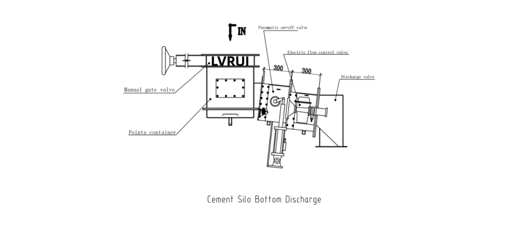
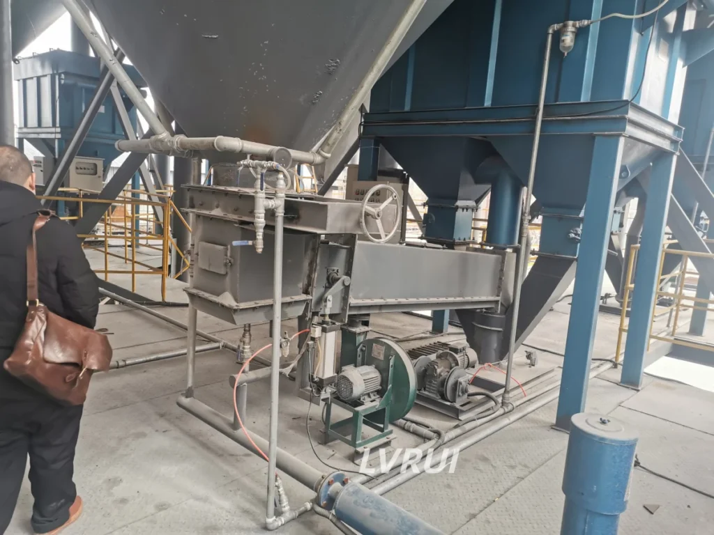
A typical silo bottom discharge arrangement can include a manual screw-operated slide gate, an aerated distribution box, pneumatic shut-off valves, motorized flow control gates, optional short air slide sections and discharge elbows. Where multiple truck loading points are required, the distribution box can be configured with up to four discharge outlets.
A silo side discharge arrangement is generally simpler. It normally uses a manual isolation gate, pneumatic shut-off valve, motorized flow control gate, optional short air slide and discharge elbow before the material enters the bulk loading spout.
The correct arrangement depends on the silo outlet, number and position of loading points, transfer distance, powder properties and available installation space.
What Is a Cement Silo Bottom Discharge Arrangement?
A silo bottom discharge arrangement is installed beneath the storage silo to control powder leaving the bottom outlet and direct it toward bulk loading equipment. This assembly forms part of a broader cement silo discharge system, with the configuration selected according to the silo outlet and truck-loading layout.
For a typical LVRUI configuration, the material path can be arranged as:
Silo Bottom Outlet → Manual Screw-Operated Slide Gate → Aerated Distribution Box → Pneumatic Shut-Off Valve → Motorized Flow Control Gate → Optional Short Air Slide → Discharge Elbow → Bulk Loading Spout → Tanker
The manual gate provides upstream isolation. The aerated distribution box assists powder movement while distributing material toward one or more discharge branches.
Each branch can then be equipped with its own shut-off and flow-control devices before connecting to the downstream loading equipment.
This configuration is particularly useful where one silo must serve several truck loading positions.
What Equipment Is Used in a Silo Bottom Discharge System?
The individual components have different functions and should not be treated as interchangeable.
| Component | Main Function |
|---|---|
| Manual screw-operated slide gate | Provides manual upstream isolation at the silo outlet |
| Aerated distribution box | Assists powder flow and distributes material to one or more discharge branches |
| Pneumatic shut-off valve | Provides automated full-open/full-close control for each discharge branch |
| Motorized flow control gate | Adjusts the effective opening to regulate powder discharge |
| Short air slide section | Transfers fluidizable powder along a suitably inclined conveying path when additional distance is required |
| Discharge elbow | Connects the discharge line to the bulk loading spout |
| Bulk loading spout | Transfers powder into the tanker while providing the final loading interface |
The combination of isolation, branch selection, discharge regulation and short-distance conveying allows the complete loading line to be controlled according to the actual plant layout.
How Does an Aerated Distribution Box Support Up to Four Discharge Outlets?
The aerated distribution box is installed below the silo bottom outlet. It introduces fluidizing air to assist the movement of suitable dry powders while distributing material into one or more discharge branches.
Depending on the project layout, LVRUI can configure the box with one, two, three or up to four outlets. Each branch can be equipped with its own pneumatic shut-off valve, motorized flow control gate, optional short air slide and discharge elbow.
This arrangement allows one silo to supply multiple loading points through separate discharge paths. However, four available outlets do not automatically mean that all four branches can operate at full capacity simultaneously. Simultaneous operation depends on the total available powder flow, aeration performance, branch capacity and control arrangement.
The final outlet quantity, branch orientation and connection dimensions should be confirmed according to the silo structure and loading-station layout.
Why Are Both a Pneumatic Shut-Off Valve and a Motorized Flow Control Gate Used?
The pneumatic shut-off valve provides automated full-open/full-close isolation for each discharge branch, while the motorized flow control gate adjusts the effective opening to regulate powder discharge.
Using both devices separates branch isolation from adjustable flow control, allowing the discharge system to perform different operating functions.
The motorized flow control gate regulates the opening but does not measure actual mass flow. Accurate dosing requires additional suitable measurement or feeding equipment.
Is a Short Air Slide Always Required?
No. A short air slide is optional and is only added when the transfer distance, installation layout and powder conveying conditions require it.
When the discharge elbow and bulk loading spout are located very close to the flow control gate, the material may be able to enter the loading equipment without an additional conveying section.
If the loading point is farther away, however, a short air slide can be added between the flow control gate and discharge elbow.
A simplified arrangement may therefore be:
Flow Control Gate → Discharge Elbow → Bulk Loader
while a longer route may use:
Flow Control Gate → Short Air Slide → Discharge Elbow → Bulk Loader
The decision should be based on the actual horizontal distance, elevation difference, powder fluidization characteristics and available installation space.
An air slide should not be added simply because it is commonly used in cement plants. It should have a clear conveying function in the actual layout.
When a short air slide is required, its inclination, conveying capacity, aeration air supply and available installation space should be checked according to the powder properties and transfer distance.
In both arrangements, the discharge elbow connects the discharge line to the cement bulk loader, which transfers powder into the tanker. The complete flow path, including the valves, optional air slide, discharge elbow and bulk loader, should be checked to ensure that the components are compatible with the required loading capacity.
What Is a Silo Side Discharge Arrangement?
Silo side discharge refers to powder leaving through a designated side outlet of the silo. It should not be confused with a side-silo bulk loader, which describes the location of the truck loading equipment relative to the silo. The two arrangements may be used together, but they refer to different parts of the material handling system.
A silo side discharge arrangement takes material from an approved outlet on the side or lower side area of the storage silo rather than through an aerated distribution box directly beneath the central outlet.
A typical configuration is:
Silo Side Outlet → Manual Screw-Operated Slide Gate → Pneumatic Shut-Off Valve → Motorized Flow Control Gate → Optional Short Air Slide → Discharge Elbow → Bulk Loading Spout → Tanker
Unlike the multi-outlet silo-bottom configuration described above, the side-discharge line normally does not require an aerated distribution box as part of this discharge assembly.
The material leaves the existing side outlet and passes directly through the isolation and flow-control equipment.
The location and structural design of any silo-side outlet must be confirmed as part of the approved silo design. The discharge equipment should be designed around that confirmed interface rather than determining the silo opening independently.
Silo Bottom vs Side Discharge: What Is the Difference?
The difference is mainly in the material-routing arrangement rather than in the basic function of the valves.
| Comparison | Silo Bottom Discharge | Silo Side Discharge |
|---|---|---|
| Typical outlet position | Below silo | Side/lower side of silo |
| Aerated distribution box | Normally included in this multi-outlet configuration | Normally not required in the discharge assembly |
| Number of discharge branches | 1–4 | Usually based on individual side outlet arrangement |
| Manual isolation | Yes | Yes |
| Pneumatic shut-off | Yes | Yes |
| Motorized flow control | Yes | Yes |
| Short air slide | Optional according to distance | Optional according to distance |
| Final connection | Discharge elbow to bulk loader | Discharge elbow to bulk loader |
| Main advantage | Flexible multi-point powder distribution | Direct connection from an approved side outlet |
Neither arrangement should be selected simply because one has fewer components.
The most suitable design depends on where the loading points are located relative to the silo and how the powder must travel between the storage outlet and tanker.
What Materials Can These Discharge Arrangements Handle?
These discharge assemblies can be used with many compatible dry powder materials, including cement, raw meal, fly ash, slag powder, limestone powder, stone powder and other fine industrial powders.
However, suitability should still be checked according to the actual material.
Important characteristics include bulk density, particle size, moisture, temperature, flowability and fluidization behavior. For suitable bulk powders, standardized testing methods such as ASTM D6393/D6393M can provide useful material-property data. However, actual aeration and discharge performance must still be evaluated for the specific application.
Dry, fluidizable powders are generally well suited to aerated distribution boxes and air slide conveying sections.
Wet, sticky, highly cohesive materials or powders containing large hardened lumps require separate evaluation because aeration and standard flow-control equipment may not solve the actual flow problem.
How to Choose Between Silo Bottom and Side Discharge?
Choose a silo-bottom arrangement when multiple loading points require a shared aerated distribution box with up to four discharge branches. A side-discharge arrangement may be more suitable when an approved side outlet provides a direct route to the loading station. Final selection should consider the silo structure, outlet location, number of loading points, transfer distance and installation space. Any new silo-side opening requires structural review.
What Information Is Required Before Designing the Discharge Assembly?
Before selecting a silo-bottom or side-discharge configuration, the following project information should be confirmed:
- Powder type, bulk density, particle size, moisture and temperature
- Required loading or discharge capacity
- Silo outlet position and connection dimensions
- Number of required discharge or loading points
- Distance from each outlet to the bulk loading spout
- Elevation difference and available installation space
- Available compressed air and electrical power
- Required local, remote or PLC control
- Bulk loader inlet/interface dimensions
- Silo layout, loading-station drawing or site photos
These data determine whether an aerated distribution box is required, how many outlets should be provided, whether each branch needs a short air slide and how the valves should connect to the loading equipment.
FAQs About Cement Silo Bottom and Side Discharge
How many outlets can a silo-bottom aerated distribution box have?
The LVRUI configuration can be designed with one, two, three or up to four discharge outlets according to the project layout. Each branch can be equipped with its own pneumatic shut-off valve and motorized flow control gate.
Does every discharge outlet need an air slide?
No. A short air slide is optional. It is mainly added when the distance between the flow-control equipment and loading point requires additional powder transfer. A nearby loading point may connect directly through the discharge elbow.
Can the same system handle fly ash or slag powder?
Yes, the discharge arrangement can be used for many compatible dry powders, including cement, raw meal, fly ash, slag powder, limestone powder and stone powder. Material flowability, moisture, temperature and fluidization characteristics should be confirmed before final design.
Is the aerated distribution box used for conveying powder?
Its primary functions are to assist powder movement through aeration and distribute material to the required discharge branches. When material needs to travel a greater horizontal distance, a separate short air slide may be added downstream.
Conclusion
Cement silo bottom and side discharge arrangements should be selected according to the silo outlet, powder properties and truck loading layout.
Bottom discharge assemblies with aerated distribution boxes support flexible multi-outlet configurations, while side-discharge assemblies provide a more direct route from an approved silo-side outlet. Proper integration of isolation valves, flow control gates, optional air slides and bulk loading equipment is essential for reliable operation.
Need Help Configuring a Silo Bottom or Side Discharge Line?
Send LVRUI your material data, silo outlet drawing and loading-point layout. We can review the required discharge branches and recommend a suitable equipment configuration.
Please provide the powder type, required capacity, silo outlet dimensions, number of loading points, outlet-to-loader distance and available electrical or compressed-air supply.
Email: info@lvrui-conveyor.com
WhatsApp: +86 18261998937
WeChat: +86 18261998937