How a sliding plate, pneumatic cylinder and ON/OFF control work together in dry bulk material handling systems
Introduction
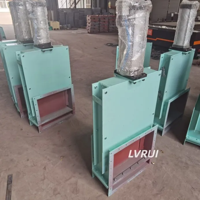
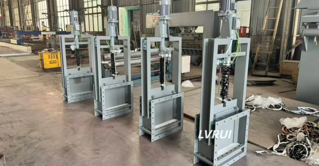
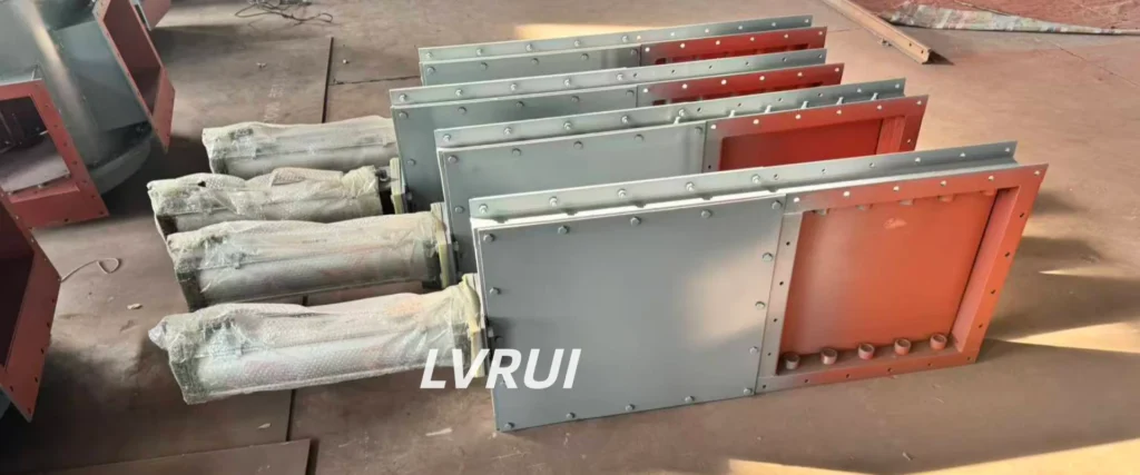
A pneumatic slide gate valve is a dry bulk material isolation device that uses a pneumatic cylinder to move a flat sliding plate between the open and closed positions.
Unlike a flow control gate designed for adjustable discharge regulation, a pneumatic slide gate is primarily used for fast ON/OFF operation. It is commonly installed beneath silos and hoppers or at conveyor and transfer connections handling cement, fly ash, lime powder, mineral powder and other compatible dry bulk materials.
Understanding its working principle and structure helps engineers select the correct valve and avoid confusing isolation, flow regulation and material-flow assistance as the same function.
How Does a Pneumatic Slide Gate Valve Work?
The working principle is based on linear movement.
When compressed air is supplied to the pneumatic cylinder, the piston moves and drives the connected gate plate along its guides.
During opening, the plate moves away from the material passage, allowing the bulk material to discharge through the valve.
During closing, the cylinder moves the plate back across the opening to shut off the material path.
A typical operating sequence is:
OPEN command → Solenoid valve switches → Cylinder moves → Gate plate retracts → Material passage opens
CLOSE command → Solenoid valve switches → Cylinder reverses → Gate plate crosses the opening → Material passage closes
Limit switches or proximity sensors can be installed to confirm the fully open and fully closed positions. These signals can be connected to a PLC or DCS when the valve is part of an automated material handling system.
The valve itself does not measure the material flow rate. Its primary function is opening, closing and isolation.
Main Components of a Pneumatic Slide Gate Valve
Although the exact design varies according to valve size and application, a typical pneumatic slide gate includes several main components.
Gate Plate
The flat sliding plate moves across the material passage. Its material and thickness should be selected according to the handled powder, particle size, abrasiveness and operating conditions.
Valve Body
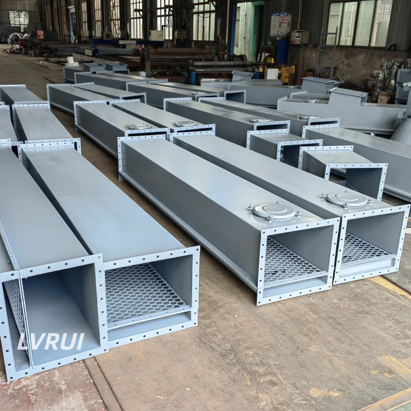
The body supports the gate plate and connects the valve to the silo, hopper, chute or conveying equipment. Square and rectangular openings are commonly used in dry bulk material systems.
Pneumatic Cylinder
The cylinder provides the linear force required to open and close the gate. Cylinder size and stroke should match the valve dimensions, material load and required operating force.
Guide and Sealing Structure
The guide system keeps the gate plate aligned during movement. The sealing arrangement helps limit powder leakage around the sliding plate.
Actual sealing performance depends on valve structure, material characteristics, wear condition and process conditions. A standard dry bulk slide gate should not automatically be treated as a zero-leakage pressure-isolation valve.
Solenoid Valve and Air Supply
A solenoid valve controls compressed air entering and leaving the pneumatic cylinder. Air pressure and air quality should meet the actuator requirements.
Position Feedback
Limit switches or proximity sensors can provide open and closed position confirmation to the plant control system.
For complete valve configurations, materials and selection information, see our Slide Gate Valve product page.
Where Are Pneumatic Slide Gate Valves Used?
Pneumatic slide gates are suitable where dry bulk material flow must be opened or stopped quickly and repeated manual operation is impractical.
Typical installation positions include:
- Cement silo outlets
- Fly ash hopper outlets
- Raw meal and powder storage hoppers
- Air slide conveyor connections
- Screw conveyor inlets or discharge points
- Powder transfer chutes
- Packing and bulk loading systems
- Weigh hopper isolation points
- Equipment isolation points for inspection or maintenance
The valve should be selected according to the actual material and operating conditions. Wet, sticky or heavily caking materials can accumulate around the sliding plate, while large hard lumps may prevent complete closing or damage the gate.
Pneumatic Slide Gate Valve vs Pneumatic Shut-Off Valve: Are They the Same?
The two terms overlap, but they do not always describe the same valve structure.
A pneumatic slide gate valve specifically uses a flat sliding plate driven linearly by a pneumatic cylinder.
A pneumatic shut-off valve is a broader functional term for a pneumatically actuated ON/OFF isolation valve. Depending on project terminology and valve design, the shut-off element may use a sliding plate or an internal arc/sector-type gate mechanism.
Therefore, a pneumatic slide gate can function as a pneumatic shut-off valve, but “pneumatic shut-off valve” should not be treated as a structural synonym for “pneumatic slide gate valve.”
For ON/OFF isolation specifically before an air slide conveyor, see our Pneumatic Shut-Off Valve for Air Slide Conveyor guide.
Pneumatic Slide Gate Valve vs Pneumatic Flow Control Gate
These two valves should not be treated as interchangeable.
| Item | Pneumatic Slide Gate Valve | Pneumatic Flow Control Gate |
|---|---|---|
| Main function | ON/OFF isolation | Adjustable discharge regulation |
| Gate movement | Linear sliding plate | Arc/sector-type regulating movement, depending on design |
| Normal operation | Mainly fully open or fully closed | Variable opening positions |
| Mass-flow measurement | No | No |
A slide gate may physically operate at an intermediate position, but this does not make it a dedicated flow control device. Stable discharge regulation depends on the valve geometry, material properties, material head and downstream system.
Where adjustable powder feeding is required, a dedicated Flow Control Gate Valve is normally more appropriate. For a detailed comparison of isolation and adjustable discharge control, see our Flow Control Gate vs Slide Gate guide.
Pneumatic Control and Automation
One advantage of pneumatic actuation is that the slide gate can be integrated into automated operating sequences.
A typical control package may include:
- Pneumatic cylinder
- Solenoid valve
- Air filter and regulator where required
- Open-position limit switch
- Closed-position limit switch
- Local control box or PLC/DCS interface
For example, a control system may allow the gate to open only after the downstream conveyor is confirmed ready. During shutdown or a fault condition, the gate can be commanded to close according to the plant interlock logic.
The exact sequence should be designed around the complete material handling system rather than the valve alone. Pneumatic system design, installation and safety should also follow the applicable machinery requirements and pneumatic safety standards. For general reference, see ISO 4414 for pneumatic fluid power systems.
What Can Cause a Pneumatic Slide Gate to Jam or Fail to Close?
If the gate does not travel smoothly or cannot reach the closed position, the cause is not always the pneumatic cylinder.
Common factors include:
- Powder buildup around the gate plate or guides
- Large particles or hardened lumps trapped in the opening
- Misalignment of the gate plate
- Insufficient pneumatic pressure
- Air leakage from tubing or fittings
- Solenoid valve malfunction
- Incorrect cylinder stroke
- Worn guide or sealing components
- Excessive material load acting on the gate
If material does not discharge even after the gate reaches the open position, the problem may instead be upstream bridging, poor aeration, compacted material or a downstream conveying restriction.
A pneumatic slide gate opens or closes the material path; it does not correct poor powder flowability by itself.
FAQs About Pneumatic Slide Gate Valves
Can a pneumatic slide gate valve be installed directly below a silo or hopper?
Yes, but the valve must be selected according to the material load above the gate, outlet size and operating conditions. A high material column can increase the force required to move the sliding plate, so the gate structure and pneumatic cylinder should be sized accordingly.
What determines the pneumatic cylinder size for a slide gate valve?
Cylinder sizing depends on the gate opening, material load, sliding resistance, sealing arrangement, required operating force and available compressed-air pressure. The cylinder should provide sufficient force to complete reliable opening and closing under actual operating conditions.
Does a pneumatic slide gate valve need position feedback?
Not always. For simple local operation, position feedback may not be necessary. In automated systems, open and closed limit switches or proximity sensors are recommended so the PLC/DCS can confirm the gate position and execute equipment interlocks.
Can pneumatic slide gate valves handle abrasive materials?
Yes, depending on the valve design and material selection. Abrasive powders or fine granular materials may require suitable gate plate materials, wear-resistant components and more frequent inspection of the guides and sealing areas.
Can a pneumatic slide gate valve be used for flow regulation?
Its primary function is ON/OFF isolation rather than continuous flow regulation. Although partial opening can restrict the material passage, a dedicated Flow Control Gate Valve is more appropriate when adjustable and repeatable powder discharge control is required.
What information is needed when replacing an existing pneumatic slide gate valve?
Provide the material, existing gate opening size, connection dimensions, installation position, available compressed-air pressure, operating frequency and required position feedback. Photos and dimensional drawings of the existing installation are also useful when checking whether a replacement valve can fit the current system.
Conclusion
A pneumatic slide gate valve uses a simple linear mechanism: a pneumatic cylinder moves a sliding plate to open or close the dry bulk material passage.
Its primary role is ON/OFF isolation. It should not be expected to provide precision dosing, correct silo bridging or replace a dedicated flow control gate where adjustable discharge regulation is required.
Correct valve selection depends on the handled material, opening size, material load, operating frequency, pneumatic supply and control requirements.
Need a Pneumatic Slide Gate Valve for Your Bulk Material System?
To recommend a suitable configuration, please provide:
- Material and bulk density
- Particle size and temperature
- Required valve opening size
- Silo, hopper or conveyor connection dimensions
- Material-column height
- Available compressed-air pressure
- Opening and closing frequency
- Required position feedback
- Site drawing, if available
LVRUI can configure the valve opening, gate plate, pneumatic cylinder, sealing arrangement and connection dimensions according to the actual application.
Email: info@lvrui-conveyor.com
WhatsApp / WeChat: +86-18261998937