How industrial flap valves control gravity discharge in cement, powder and bulk-solid handling systems, including single-flap, double-flap, pneumatic and electric configurations.
Introduction
Industrial flap valves are commonly used at gravity-discharge points in cement plants, dust collection systems and other dry bulk material handling processes.
Their main function is to open and close a material passage so that powder or granular material can discharge from a hopper, chute or process vessel into downstream equipment.
However, not all flap valves operate in the same way. Some rely on gravity and a counterweight, while others use pneumatic cylinders or electric actuators. Single-flap and double-flap designs also provide different levels of flow isolation and air-leakage control.
For this reason, flap valve selection should be based on the actual material, operating pressure, discharge method, required capacity and installation conditions rather than simply choosing a valve by nominal size.
This article explains how industrial flap valves work, where different configurations are used and how to select a suitable design for bulk powder handling.
What Is an Industrial Flap Valve?
An industrial flap valve is a mechanical discharge valve that uses one or more hinged flaps to open or close a material passage.
It is commonly installed below:
- hoppers;
- dust collector discharge points;
- cyclones;
- storage bins;
- chutes;
- gravity-fed bulk material systems.
When the flap opens, material passes through the valve. When the flap returns to the closed position, it interrupts or restricts the passage between the upstream and downstream equipment.
The actual operating function depends on the valve design. A simple single-flap valve may be used mainly for gravity discharge, while a double-flap arrangement can provide improved separation between upstream and downstream zones by operating two flap stages alternately.
How Does an Industrial Flap Valve Work?
The working principle depends on how the flap is actuated.
Gravity or Counterweighted Operation
In a gravity-operated design, material accumulates above the flap until its weight creates enough force to open the valve.
The typical cycle is:
- Bulk material enters the valve or discharge chamber.
- Material weight acts on the flap.
- The flap opens when the opening force exceeds the closing force.
- Material discharges through the valve.
- As the material load decreases, the flap returns toward the closed position.
A counterweight can be used to adjust the closing force and influence when the flap opens.
This arrangement does not require an electric motor for flap movement, but it should not be assumed that every industrial flap valve operates without external power.
Pneumatic or Electric Operation
Where controlled opening and closing are required, the flap can be operated by a pneumatic cylinder or electric actuator.
Actuated valves are useful when the plant control system needs to coordinate material discharge with:
- upstream equipment;
- downstream conveyors;
- process interlocks;
- level signals;
- sequence control.
The actuator type should therefore be selected according to the required control method rather than treated as a simple replacement for gravity operation.
Types of Industrial Flap Valves
Single-Flap Valve
A single-flap valve uses one hinged flap to open and close the material passage.
It is commonly considered where the process requires:
- simple gravity discharge;
- intermittent material release;
- relatively simple mechanical construction;
- limited air-isolation requirements.
Its suitability depends on material size, loading condition and pressure difference across the valve.
Double-Flap Valve
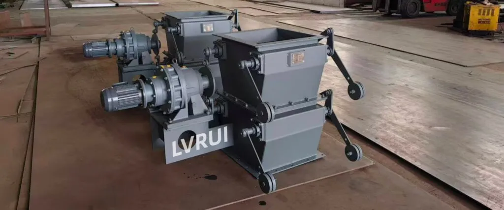
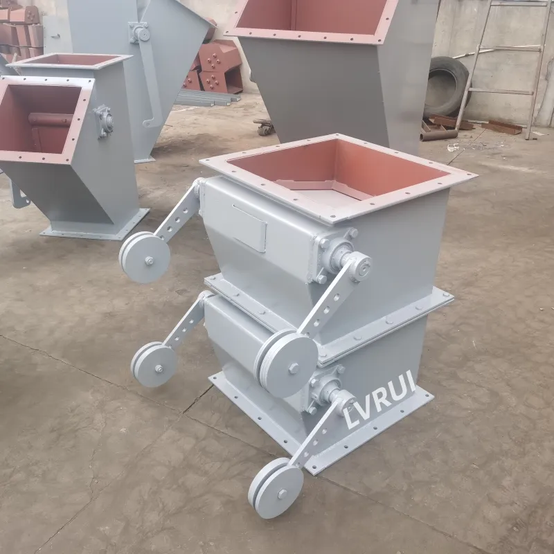
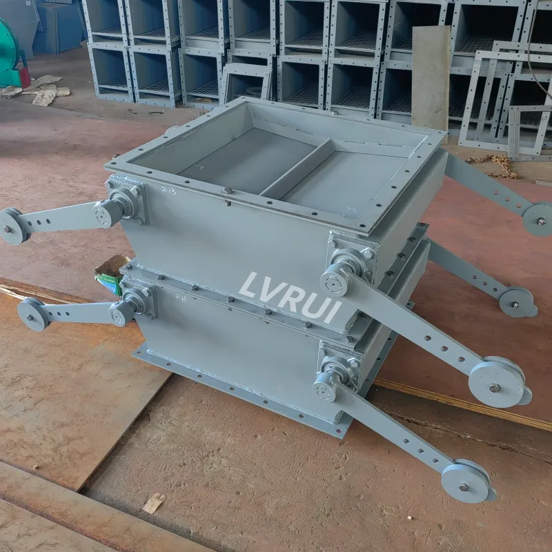
A double-flap valve uses two flap stages arranged vertically.
During operation, the two flaps can open and close alternately so that one stage remains closed while material passes through the other.
This arrangement can reduce direct air passage between the upstream and downstream sides compared with a simple single-flap design.
Double-flap valves are therefore often considered where:
- material must discharge intermittently;
- some pressure separation is required;
- air leakage should be reduced;
- the process does not require continuous rotary feeding.
Avoid describing a double-flap valve as completely airtight unless the actual design and operating condition support that claim.
Pneumatic Flap Valve
A pneumatic flap valve uses a cylinder to control flap movement.
It is suitable when the opening and closing sequence must be controlled from a local panel or plant control system.
Important considerations include:
- available compressed air;
- cylinder stroke;
- opening and closing time;
- control signal;
- fail position;
- operating frequency.
Electric Flap Valve
An electric flap valve uses an electric actuator or other motorized drive to control flap movement.
This configuration can be considered where compressed air is unavailable or where the valve must be integrated into an electrical control system.
Selection should confirm:
- actuator torque;
- power supply;
- open/close or modulating requirement;
- local/remote control;
- operating frequency.
Main Components of an Industrial Flap Valve
Depending on the configuration, an industrial flap valve may include:
| Component | Function |
|---|---|
| Valve housing | Forms the material passage and supports the flap mechanism |
| Flap plate | Opens and closes the discharge passage |
| Shaft and bearings | Support flap rotation |
| Counterweight | Provides adjustable closing force in gravity-operated designs |
| Pneumatic cylinder | Controls flap movement in pneumatic versions |
| Electric actuator | Provides motorized opening and closing |
| Sealing/contact surfaces | Help reduce material and air leakage when the flap is closed |
| Position or limit devices | Provide open/closed feedback where required |
The exact structure varies between single-flap, double-flap and actuated configurations.
Typical Applications in Bulk Powder Handling
Dust Collector Hopper Discharge
Flap valves can be installed below dust collector or cyclone hoppers to discharge collected dust into downstream equipment.
In this application, the valve should be selected according to:
- dust characteristics;
- discharge frequency;
- hopper pressure condition;
- downstream equipment;
- required air-leakage control.
Silo and Hopper Gravity Discharge
Flap valves can be used at gravity-discharge points where dry bulk material needs to be released into a chute, conveyor or receiving equipment.
The valve opening and material passage must be large enough for the actual particle size and flow conditions.
Cement and Mineral Powder Handling
In cement, fly ash, lime and mineral powder systems, flap valves may be used where intermittent gravity discharge or material isolation is required.
Fine powders require particular attention to dust leakage and material buildup around the flap and sealing surfaces.
Granular Bulk Materials
Flap valves can also handle certain granular materials, provided that the opening size and flap structure are suitable for the maximum particle size.
Large or irregular particles should be checked carefully because they can become trapped between the flap and housing during closing.
Can a Flap Valve Be Used as an Airlock?
A flap valve can reduce air leakage when the flap is closed, but its airlock performance depends strongly on the valve design and operating condition.
A single-flap gravity valve should not automatically be treated as an airtight isolation device.
A double-flap valve can provide better pressure separation because the two flaps can operate alternately, reducing the time that the upstream and downstream sides are directly connected.
However, the suitability of any flap valve for a system with pressure differential should be verified according to:
- operating pressure;
- allowable air leakage;
- flap sealing structure;
- material buildup;
- cycling frequency;
- required discharge rate.
For applications requiring continuous feeding with controlled air leakage, a rotary airlock valve may be more appropriate.
Flap Valve vs Rotary Airlock Valve
Both flap valves and rotary airlock valves can be used at bulk-material discharge points, but their operating principles are different.
| Comparison | Flap Valve | Rotary Airlock Valve |
|---|---|---|
| Operating principle | Hinged flap opens and closes the material passage | Rotating pockets continuously transfer material |
| Material discharge | Usually intermittent or cyclic | More continuous |
| Drive | Gravity, pneumatic or electric depending on design | Normally motor and gearbox |
| Air isolation | Depends strongly on flap arrangement and sealing | Designed to limit air leakage during continuous rotation |
| Particle handling | Depends on flap opening and clearance | Limited by rotor pocket and rotor-to-housing clearance |
| Metering capability | Limited | Can provide more controlled volumetric feeding |
| Mechanical structure | Relatively simple in basic designs | More rotating components and close clearances |
| Typical use | Gravity discharge, dust hopper discharge, intermittent transfer | Continuous feeding and airlock applications |
Neither valve type is universally better.
The correct choice depends on whether the process requires intermittent discharge, continuous feeding, pressure separation, metering or tolerance for larger particles.
OSHA’s technical guidance on dry-type dust collector discharge valves also illustrates the different operating roles of trickle valves, rotary locks and double-dump valves.
How to Select an Industrial Flap Valve
Valve selection should start with the actual material and process conditions.
1. Material Type
Identify whether the valve will handle:
- cement;
- fly ash;
- lime;
- mineral powder;
- dust;
- granules;
- other dry bulk solids.
Material behavior affects flap movement, wear and sealing performance.
2. Maximum Particle Size
The valve opening must provide sufficient clearance for the largest expected particles.
Oversized or irregular particles can prevent the flap from closing correctly.
3. Bulk Density
Bulk density influences the force acting on gravity-operated flaps and should be considered when setting counterweight or flap balance.
4. Required Capacity
Confirm both normal and maximum discharge rate.
The selected valve must provide sufficient opening area without creating an unnecessary restriction in the material flow path.
5. Material Temperature
Temperature affects:
- flap materials;
- bearings;
- flexible components;
- sealing materials;
- actuator selection.
Do not specify a generic maximum temperature without confirming the final construction.
6. Abrasion
Abrasive materials may require wear-resistant plate, liners or replaceable contact components at high-wear areas.
7. Pressure Conditions
Confirm the pressure on both sides of the valve and the acceptable air-leakage level.
This is particularly important when selecting between single-flap, double-flap and rotary airlock arrangements.
8. Actuation Method
Choose between:
- gravity / counterweight;
- pneumatic cylinder;
- electric actuator.
The selection should match the required operating sequence and available utilities.
9. Installation Interface
Confirm:
- inlet size;
- outlet size;
- flange arrangement;
- available installation height;
- downstream equipment;
- maintenance access.
10. Control Requirements
For actuated valves, confirm:
- local or remote operation;
- open/closed feedback;
- interlocks;
- voltage;
- compressed-air availability.
When Is a Flap Valve Not the Right Choice?
A flap valve may not be the best option when:
- precise continuous metering is required;
- the process requires very low and tightly controlled air leakage;
- material is highly sticky and prevents reliable flap closure;
- oversized particles cannot pass through the available valve opening;
- continuous feeding is more important than intermittent discharge;
- the operating pressure exceeds the capability of the selected flap-valve design.
In these cases, equipment such as a rotary valve, slide gate, feeder or another discharge device may be more suitable depending on the process.
Where a flap valve is not suitable, other industrial valves for bulk material handling should be compared according to the required shut-off, flow-control or feeding function.
FAQs About Industrial Flap Valves
Can an industrial flap valve be retrofitted to an existing hopper or dust collector?
Yes, in many cases. Retrofit feasibility depends on the existing discharge opening, flange dimensions, available installation height, supporting structure and downstream equipment. The original layout should be checked before determining the valve size and connection arrangement.
What can prevent a flap valve from closing completely?
Common causes include oversized particles trapped at the flap, material buildup on contact surfaces, shaft or bearing wear, incorrect counterweight adjustment, flap misalignment or insufficient actuator force. The actual cause should be identified before changing the actuator or counterweight setting.
What happens if compressed air is lost on a pneumatic flap valve?
The response depends on the cylinder and control arrangement. The flap may remain in its current position or move to a defined fail position if the system is designed for that function. The required fail-safe condition should therefore be confirmed during valve selection.
Can an industrial flap valve be installed in any orientation?
Not always. Gravity- and counterweight-operated flap valves depend on the installation orientation, material flow direction and flap movement to operate correctly. If the valve must be installed on an inclined or unusual discharge path, the geometry should be checked before manufacturing.
What parts of an industrial flap valve require regular inspection?
Typical inspection points include the flap plate, shaft, bearings, contact or sealing surfaces, counterweight mechanism, pneumatic cylinder or electric actuator, limit switches and areas where powder can accumulate. Wear and buildup should be corrected before they affect flap movement.
How often should an industrial flap valve be inspected?
Inspection frequency depends on operating cycles, material abrasiveness, temperature and dust buildup. Valves handling abrasive materials or operating at high cycling frequency should be checked more frequently than lightly loaded gravity-discharge valves. The maintenance interval should be adjusted according to actual wear observed during service.
Conclusion
Industrial flap valves provide a relatively simple way to control gravity discharge in cement, powder and bulk-solid handling systems.
However, valve performance depends on selecting the correct configuration for the actual process.
Single-flap, double-flap, gravity-operated, pneumatic and electric designs each have different operating characteristics. Material type, particle size, bulk density, temperature, abrasion, required capacity, pressure conditions and control requirements should all be confirmed before final selection.
Where pressure isolation or continuous feeding is critical, the flap valve should also be compared with alternatives such as rotary airlock valves rather than selected on cost or simplicity alone.
Need Help Selecting an Industrial Flap Valve?
Send us your material type, bulk density, maximum particle size, material temperature, required discharge capacity, inlet and outlet dimensions, pressure conditions and preferred operating method.
LVRUI can review these parameters and help determine whether a single-flap, double-flap, pneumatic, electric or another bulk-material discharge valve is more suitable for your application. We can then provide a recommended configuration, technical drawing and quotation.
Contact Us: https://lvrui-conveyor.com/contact-us/
Email: info@lvrui-conveyor.com
WhatsApp: +86-18261998937
WeChat: +86-18261998937