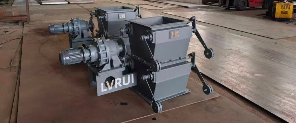
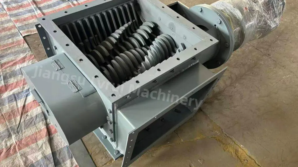
How blade rotation, shaft position and actuator movement change the effective duct opening to regulate or isolate air, exhaust gas and dust-laden airflow.
Introduction
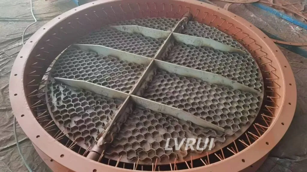
Butterfly damper working principle is based on a simple mechanical action: a single blade rotates around a shaft inside an industrial air duct to change the available flow area.
When the blade moves toward the open position, airflow resistance decreases and more air or gas can pass through the duct. As the blade rotates toward the closed position, the effective opening becomes smaller and airflow is restricted.
The blade can be positioned manually or moved by an electric or pneumatic actuator depending on the required operating method.
Butterfly dampers are commonly used in dust collection, ventilation, exhaust and process-air systems where airflow needs to be regulated or isolated. They are designed mainly for air and gas service rather than direct cement powder or bulk-solid discharge. Butterfly dampers are one of the main types of industrial damper valves used for airflow regulation and duct isolation.
How Does a Butterfly Damper Work?
The butterfly damper working principle relies on a circular or shaped blade rotating around a shaft inside the duct.
The basic operating sequence is:
- The actuator or manual mechanism applies torque to the shaft.
- The shaft rotates the damper blade.
- Blade rotation changes the effective flow area inside the duct.
- The change in flow area alters airflow resistance.
- The final blade position determines whether the damper is mainly regulating airflow or isolating the duct.
When the blade is aligned more closely with the airflow direction, resistance is relatively low.
When the blade rotates across the duct, the available flow area becomes smaller and airflow is increasingly restricted.
At the closed position, the blade blocks most of the duct cross-section. Actual leakage depends on blade clearance, sealing design, duct pressure and operating condition.
How Blade Position Changes Airflow
Butterfly dampers do not normally provide a linear relationship between blade angle and airflow.
A small change in blade position near the fully open condition may have a different effect on airflow than the same angular movement near the more closed position.
Actual airflow response depends on:
- duct size;
- air velocity;
- system resistance;
- fan operating point;
- blade geometry;
- pressure difference;
- upstream and downstream duct conditions.
For this reason, blade position alone should not be treated as a direct measurement of airflow volume.
If accurate airflow control is required, the damper position should be coordinated with the fan system, pressure measurement or other process-control signals.
Main Components That Affect Butterfly Damper Operation
| Component | Function |
|---|---|
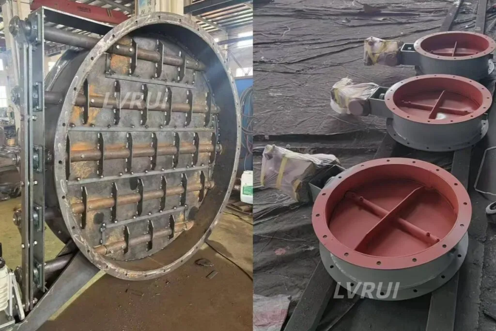
| Damper Body | Forms the duct section and supports the blade and shaft |
| Damper Blade | Changes the effective airflow opening |
| Shaft | Transfers torque from the operating mechanism to the blade |
| Bearings | Support shaft rotation |
| Sealing Arrangement | Helps reduce leakage when the damper approaches the closed position |
| Manual Mechanism or Actuator | Moves and positions the blade |
| Position Feedback Device | Provides open/closed or intermediate position feedback where required |
The interaction between the blade, shaft, bearings and actuator determines how smoothly the damper moves and how accurately the required position can be maintained.
How Manual, Electric and Pneumatic Actuation Works
In the butterfly damper working principle, the actuator or manual mechanism provides the torque required to rotate and position the blade.
Manual Operation
A manual butterfly damper is positioned using a lever, handwheel or gearbox.
The operator rotates the mechanism until the required blade position is reached.
Manual operation is suitable where blade position changes infrequently and remote control is not required.
Electric Actuator
An electric actuator applies controlled torque to the damper shaft.
Depending on the actuator configuration, the damper can operate in:
- open/close mode;
- intermediate positioning;
- local or remote control;
- modulating control.
For centralized plant control, position signals such as 4–20 mA may be used where required.
Pneumatic Actuator
A pneumatic actuator uses compressed air to rotate or move the damper shaft.
Pneumatic operation is often used where relatively fast opening and closing or automatic interlocking is required.
The final operating speed depends on actuator size, air pressure, solenoid configuration and damper load.
Airflow Regulation vs Duct Isolation
A butterfly damper can perform two related but different functions.
Airflow Regulation
For regulation, the blade operates at intermediate positions to change airflow resistance and adjust the amount of air passing through the duct.
Duct Isolation
For isolation, the blade moves toward the closed position to restrict airflow through the duct section.
However, a standard butterfly damper should not automatically be considered airtight. Standardized damper testing methods such as ANSI/AMCA Standard 500-D are used to evaluate parameters including airflow performance, pressure drop and leakage under defined test conditions.
The actual leakage level depends on:
- blade-to-body clearance;
- sealing design;
- shaft sealing;
- operating pressure;
- temperature;
- dust buildup;
- mechanical alignment.
If low leakage or a specific shut-off requirement is critical, it should be defined separately during damper design.
What Operating Conditions Affect Butterfly Damper Performance?
Duct Pressure
Pressure difference across the blade affects shaft load and required actuator torque.
Airflow Velocity
Higher airflow velocity increases aerodynamic forces acting on the blade and may influence vibration, operating torque and pressure loss.
Dust Concentration
Dust-laden airflow can cause buildup around the blade, shaft or sealing areas, especially where dust is sticky or abrasive.
Temperature
Elevated temperature can affect body material, shaft expansion, bearings, sealing components and actuator installation.
Operating Frequency
Frequently cycled dampers require more attention to shaft support, bearings, actuator sizing and maintenance access.
Duct Geometry
Elbows, transitions, fans or other equipment installed close to the damper can create uneven airflow and affect damper performance.
Typical Applications of Butterfly Dampers
Butterfly dampers are commonly used where industrial airflow must be regulated or isolated.
Typical applications include:
Dust Collection Ducts
The damper can regulate or isolate airflow in dust collector inlet, outlet or branch ducts.
Fan Inlet and Exhaust Ducts
Blade position can be used to adjust airflow or isolate a fan-related duct section.
Cement Plant Ventilation
Butterfly dampers can be used in mill ventilation, transfer-point dust extraction and other process-air duct systems.
Air Slide Blower and Process-Air Ducts
In an air slide system, the butterfly damper can regulate the air supplied from the blower to the lower aeration chamber.
It controls the airflow, not the cement powder moving above the air slide fabric.
Kiln, Cooler and Process Exhaust
Where temperature, dust concentration and pressure conditions are suitable, butterfly dampers can be used in exhaust or process-gas duct systems.
Butterfly Damper vs Louver Damper: Different Working Mechanisms
A butterfly damper uses one rotating blade, while a louver damper valve uses multiple linked blades.
The butterfly structure is compact and mechanically simple, while the louver structure distributes airflow control across several blades.
For a detailed selection comparison, see our Butterfly Damper Valve vs Louver Damper Valve guide.
Conclusion
Butterfly damper working principle is based on rotating a single blade inside the duct to change the effective airflow opening.
The blade position affects airflow resistance, while the shaft and actuator determine how the damper moves and holds its required position.
Actual performance depends on more than blade angle alone. Duct pressure, airflow velocity, temperature, dust concentration, sealing design and nearby duct geometry can all influence operation.
Understanding these factors helps engineers apply butterfly dampers correctly for airflow regulation and duct isolation without treating them as bulk-solid control valves or inherently airtight shut-off devices.
FAQs About Butterfly Damper Working Principle
Why does butterfly damper airflow not change linearly with blade angle?
Because airflow depends on the complete duct system, not blade angle alone. Fan performance, duct resistance, pressure difference, blade geometry and nearby elbows or transitions can all affect how airflow responds to a change in blade position.
What can cause a butterfly damper blade to become difficult to move?
Common causes include dust buildup, bearing contamination, shaft misalignment, thermal deformation, mechanical interference or insufficient actuator torque. The actual cause should be checked before increasing actuator size.
How can I confirm whether the butterfly damper is fully open or closed?
Mechanical stops, limit switches or position indicators can be used to confirm blade position. For automated systems, open/close feedback or continuous position feedback can also be integrated into the control system.
Can an existing manual butterfly damper be converted to electric or pneumatic operation?
In many cases, yes, provided that the shaft, mounting arrangement and required operating torque are suitable for the new actuator. If automation is planned later, actuator mounting and shaft design should be considered in advance.
Why can leakage increase after long-term butterfly damper operation?
Leakage may increase because of blade wear, dust buildup, damaged sealing components, shaft misalignment or thermal deformation. Inspection should focus on the blade edge, body contact area, shaft seals and closing position.
Does the installation position in the duct affect butterfly damper performance?
Yes. Elbows, transitions, fans or other equipment installed too close to the damper can create uneven airflow and affect pressure loss, vibration and regulation performance. Duct layout should therefore be considered when selecting the installation position.
Need Help Evaluating Butterfly Damper Operation?
Send us your duct dimensions, airflow volume, operating temperature, pressure condition, dust or gas characteristics and required control method.
LVRUI can review the operating conditions and help determine whether the existing butterfly damper configuration, blade arrangement and actuator method are suitable for your airflow-control application.
For new equipment selection and quotation, see our Butterfly Damper Valve product page.
Contact Us: https://lvrui-conveyor.com/contact-us/
Email: info@lvrui-conveyor.com
WhatsApp: +86-18261998937
WeChat: +86-18261998937