How pneumatic actuation, air supply, position control and PLC logic work together in dry bulk powder discharge systems
Introduction
The pneumatic flow control gate working principle is based on compressed-air actuation that adjusts the discharge opening beneath cement silos, fly ash silos, powder hoppers, and other dry bulk storage equipment.
Unlike a simple shut-off gate, a flow control gate can be configured to change the effective discharge opening so that the amount of material entering downstream equipment can be adjusted according to process requirements.
However, the pneumatic actuator does not directly measure or determine the mass flow of powder. It controls the gate position. Actual discharge also depends on material flowability, bulk density, silo head, aeration condition, gate opening, and downstream resistance.
Understanding this distinction is essential when integrating a pneumatic flow control gate into an automated silo discharge or conveying system.
What Is a Pneumatic Flow Control Gate?
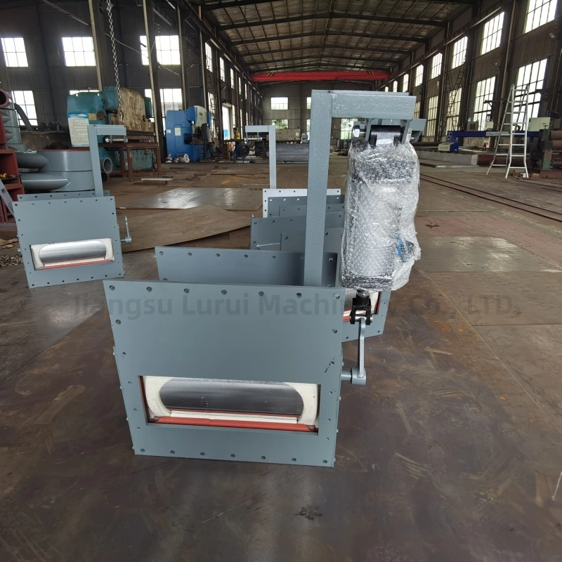
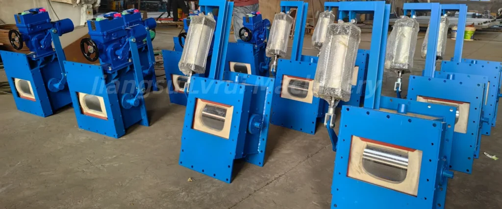
A pneumatic flow control gate is an air-operated dry bulk material flow-control device used to adjust the discharge opening beneath a silo, hopper, or powder handling system.
Compressed air drives the pneumatic actuator, allowing the gate to move between operating positions without manual adjustment. Depending on the actuator and control configuration, the gate may operate in simple open-close mode or at adjustable intermediate positions.
For product specifications, dimensions, actuator options, and commercial selection, refer to the Pneumatic Flow Control Gate Valve product page.
Pneumatic Flow Control Gate Working Principle
The working principle is based on converting compressed-air energy into mechanical movement of the flow-control mechanism.
When the control system sends an operating command, the pneumatic control circuit directs compressed air to the actuator. The actuator then moves the internal gate mechanism toward the required opening position.
As the effective discharge opening changes, the available passage for dry bulk material also changes.
The basic operating sequence is:
Control command → pneumatic valve response → actuator movement → gate position change → position confirmation → material discharge
When position feedback or limit switches are provided, the control system can confirm whether the gate has reached the required position before continuing the next process step.
The gate therefore controls the discharge opening rather than directly measuring the material flow rate.
Main Components of the Pneumatic Control System
A reliable pneumatic flow control gate depends on more than the valve body itself.
| Component | Main Function |
|---|---|
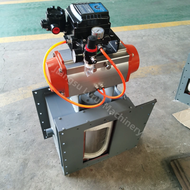
| Pneumatic actuator | Converts compressed air into mechanical movement |
| Solenoid valve | Directs the pneumatic control signal to the actuator |
| Air preparation components | Help provide suitable air quality and stable operating conditions |
| Positioner | Allows controlled intermediate positioning when required |
| Limit switches | Confirm defined end positions |
| Position feedback | Reports gate position to the control system |
| Local control station | Allows nearby manual operation during commissioning or maintenance |
| PLC / DCS interface | Provides remote commands, interlocks and process sequencing |
The exact arrangement depends on whether the application requires simple open-close operation or adjustable positioning.
Open-Close Operation vs Adjustable Positioning
Pneumatic flow control gates can be configured for different control requirements.
Open-Close Operation
In a basic pneumatic configuration, the actuator moves the gate between defined open and closed positions.
This arrangement is suitable where the process mainly requires remote starting and stopping of material discharge.
Adjustable Intermediate Positioning
Where the discharge opening must be adjusted, a suitable pneumatic or electropneumatic positioning system can be used.
Depending on the configuration, the control system may command different gate positions and receive feedback indicating the actual position.
Intermediate positioning can help adjust the discharge opening, but it should not be confused with precision mass-flow measurement.
A 50% gate position does not automatically mean 50% of maximum material flow.
Why Gate Position Does Not Equal Material Flow Rate
This is one of the most important points in pneumatic flow control gate operation.
The actual discharge rate depends on several interacting conditions:
| Factor | Effect on Discharge |
|---|---|
| Bulk density | Changes the mass passing through a given opening |
| Powder flowability | Affects how freely the material leaves the silo |
| Material head | Changes the load above the discharge point |
| Aeration condition | Can significantly change powder flow behavior |
| Gate opening | Changes the available discharge area |
| Downstream resistance | Can restrict the actual material discharge |
| Material condition | Cohesion or compaction may change discharge behavior |
For this reason, the gate should be treated as a discharge-opening control device, not as an independent weighing or metering instrument.
Where precise mass-flow measurement is required, suitable weighing, feeding, or process-feedback equipment should be used as part of the complete system.
Air Supply and Pneumatic System Requirements
Reliable operation depends on a stable and correctly configured compressed-air system.
The required operating pressure should be confirmed according to the actuator design, required output torque or force, gate size, mechanical resistance, operating frequency, and control configuration.
Using higher air pressure is not an appropriate solution for every operating problem.
If the actuator does not reach the commanded position, engineers should first check mechanical alignment, abnormal resistance, material buildup, pneumatic leakage, control-valve condition, and actuator sizing.
The pneumatic system should also consider air cleanliness, moisture, pipe sizing, fittings, control-valve capacity, and required response time.
For general pneumatic system design and safety principles, see ISO 4414 pneumatic fluid power safety requirements, which covers general rules and safety requirements for pneumatic systems and their components.
Pneumatic Actuator Sizing Considerations
The actuator should not be selected only according to the nominal gate size.
The required actuator output depends on the complete mechanical and operating condition.
Important factors include the gate mechanism, material load, friction, mechanical transmission, required operating speed, operating frequency, differential loading, installation condition, and an appropriate engineering margin.
An actuator that is too small may fail to reach the required position under actual operating conditions.
At the same time, selecting an unnecessarily oversized actuator does not solve poor gate alignment, excessive mechanical resistance, or material buildup.
The final actuator configuration should therefore be confirmed together with the gate manufacturer and project operating data.
Position Feedback and Limit Switches
Limit switches and position feedback perform different functions.
A limit switch is normally used to confirm a defined condition such as fully open or fully closed.
Position feedback provides information about the actual operating position of the gate and is useful when intermediate positioning or remote monitoring is required.
Depending on the actuator and control configuration, signals may include open confirmation, closed confirmation, intermediate position feedback, local position indication, or an analog control/feedback signal.
Not every project requires all of these functions.
The control interface should be selected according to the actual automation requirement.
PLC Control Logic for Silo Discharge
A pneumatic flow control gate can be integrated into a PLC-controlled silo discharge sequence.
A typical sequence may begin by confirming that downstream conveying or loading equipment is ready. The PLC then verifies required permissive conditions and sends an operating command to the pneumatic system.
After the actuator moves the gate, the required limit switch or position feedback confirms the operating state. Material discharge can then continue according to the process sequence.
When the discharge operation ends, the PLC commands the gate to return to the required position and verifies the corresponding feedback signal.
If movement is commanded but the expected position is not confirmed within the defined time, the control system can generate an alarm or stop the sequence.
The exact logic should always be designed according to the complete plant process rather than copied as a universal control program.
Common Pneumatic Control Problems
The Gate Does Not Move
Check the compressed-air supply, solenoid valve, electrical control signal, actuator condition, mechanical resistance, and process interlocks.
The Gate Moves Too Slowly
Check available air pressure, pneumatic restrictions, pipe and fitting size, control-valve condition, actuator loading, and mechanical friction.
The Gate Does Not Reach the Commanded Position
Check actuator travel, mechanical alignment, position settings, abnormal resistance, material buildup, and whether the actuator output is adequate for the operating condition.
Position Feedback Does Not Match the Actual Gate Position
Inspect sensor or positioner calibration, mechanical coupling, wiring, feedback scaling, and actual gate movement.
The Pneumatic System Operates Unsteadily
Check pressure fluctuations, air leakage, moisture contamination, valve response, actuator condition, and mechanical resistance.
For mechanical sticking, leakage, irregular discharge, or other valve-side problems, refer to the Flow Control Gate Troubleshooting guide.
Typical Applications
Pneumatic flow control gates are commonly used where dry powder discharge requires remote or automated operation, including:
- Cement silo discharge
- Fly ash silo discharge
- Raw meal and mineral powder handling
- Air slide or screw conveyor feeding points
- Automated bulk loading and conveying systems
Suitability depends on available compressed air, operating frequency, control mode, material condition, and downstream equipment.
Pneumatic vs Motorized Flow Control Gate
Pneumatic and motorized flow control gates can perform similar discharge-control functions, but their actuation methods differ.
Pneumatic actuation is commonly considered where plant compressed air is available and relatively fast or frequent operation is required.
Motorized actuation is commonly considered where electrical operation, controlled positioning, or operation without a plant compressed-air supply is preferred.
The final choice should be based on process requirements rather than assuming that one drive type is universally better.
For a detailed comparison, see Pneumatic vs Motorized Flow Control Gate.
Information Needed for Pneumatic Gate Configuration
Before confirming the pneumatic configuration, engineers should define the material, bulk density, silo or hopper outlet dimensions, expected discharge capacity, available compressed-air conditions, required operating frequency, open-close or positioning requirement, feedback requirement, PLC interface, downstream equipment, and available installation space.
These parameters allow the gate body, actuator, control components, and installation arrangement to be evaluated together.
For a broader comparison of manual, pneumatic and motorized configurations, see our Flow Control Gate Selection Guide.
FAQs About Pneumatic Flow Control Gate Working Principle
What happens if the compressed-air pressure is unstable?
Unstable air pressure can cause slow, incomplete, or inconsistent actuator movement. The air supply, regulator, piping, leakage, and actuator load should be checked before adjusting the operating pressure.
Can an existing manual flow control gate be converted to pneumatic operation?
In some cases, yes. The gate structure, shaft or transmission arrangement, available installation space, required actuator output, and mounting interface must first be checked to determine whether a retrofit is practical.
What should be checked if the pneumatic gate operates normally when empty but struggles under material load?
Check material load on the gate mechanism, mechanical friction, alignment, buildup around moving parts, available actuator output, and actual compressed-air pressure under operating conditions.
How often should the pneumatic control components be inspected?
Inspection frequency depends on operating cycles, dust conditions, and plant maintenance practice. Typical checks include air leakage, solenoid valve response, actuator movement, fittings, sensors, and position feedback.
Can a pneumatic flow control gate remain in position if the air supply is lost?
It depends on the actuator and control configuration. The required fail position—open, closed, or remain in place—should be defined during system design and confirmed with the actuator arrangement.
Can a pneumatic flow control gate be used with both air slides and screw conveyors?
Yes, provided the gate is correctly sized and the downstream equipment can accept the resulting material discharge. The gate controls the discharge opening, while actual flow also depends on the material and downstream system.
Conclusion
Understanding the pneumatic flow control gate working principle requires considering the complete actuation and control system, including the actuator, air supply, control valve, positioner, feedback devices, and PLC logic.
The actuator controls the gate opening rather than directly determining the mass flow of powder. Actual discharge remains dependent on material properties, silo conditions, aeration, and downstream resistance.
For this reason, the pneumatic gate should be evaluated as part of the complete silo discharge and conveying system rather than as an isolated flow-measuring device.
Need Help Configuring a Pneumatic Flow Control Gate?
For a pneumatic flow control gate project, provide the material name, bulk density, silo or hopper outlet dimensions, required discharge capacity, available compressed-air conditions, required operating frequency, control mode, position-feedback requirements, downstream equipment, and installation drawing.
LVRUI can review these operating conditions and help determine the appropriate flow control gate configuration, pneumatic actuator arrangement, position-control requirements, and interface with the plant control system.
WhatsApp / WeChat: +86-18261998937
Email: info@lvrui-conveyor.com