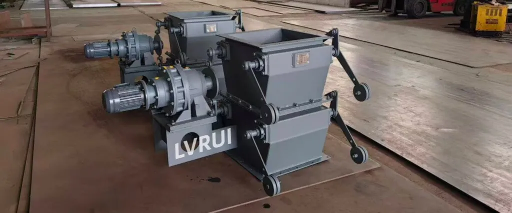
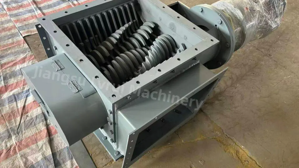
Practical hopper outlet layouts combining parallel-rod isolation with downstream gravity-discharge gates

Introduction
A rod gate for hopper discharge is used to isolate coarse or lumpy bulk materials at silo, hopper and bunker outlets. In cement plants and aggregate handling facilities, material isolation and downstream discharge control are often handled by separate devices.
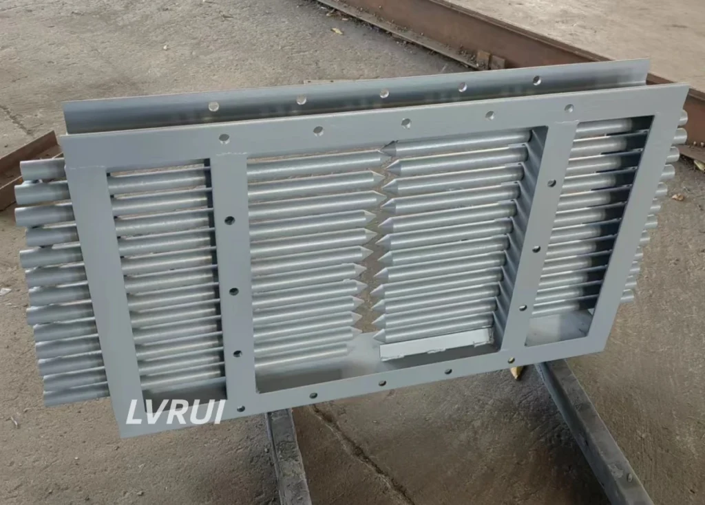
Rod gates use parallel withdrawable steel rods to support the stored material and open the discharge passage. They are commonly combined with sector gates or clamshell gates, which can be configured to control material release into downstream equipment.
This article focuses on how these gates work together in clinker and aggregate discharge applications, including typical layouts, installation considerations and operating requirements.
What Is a Rod Gate Used for in Hopper Discharge?
A rod gate is a bulk material isolation device installed across a hopper or silo outlet. Its parallel steel rods support the stored material when inserted and create a discharge opening when withdrawn.
Rod gates are primarily used for clinker, aggregates, crushed limestone and other coarse or lumpy bulk solids.
In a combined discharge arrangement, the rod gate provides material isolation, while a separate downstream gate handles the required discharge-control function.
This separation allows the equipment configuration to be adapted to the material characteristics, outlet dimensions and operating requirements.
For product configurations and manufacturing information, see LVRUI’s rod gate equipment.
How Does a Rod Gate Work at a Hopper Outlet?
When the gate is closed, parallel steel rods extend across the discharge opening to support the stored bulk material.
During opening, the rods are withdrawn individually or in groups, depending on the selected configuration.
The withdrawal direction, available operating space and material load must be considered when designing the installation.
Once the rods have been withdrawn, material can pass through the opening to the downstream discharge gate.
The rod gate itself is not intended for precise flow regulation or tight sealing of fine powders. Discharge characteristics depend on the material and the complete equipment arrangement.
Typical Rod Gate and Downstream Gate Arrangement
In a typical rod gate for hopper discharge arrangement, the gate can be combined with a sector gate or clamshell gate to separate upstream material isolation from downstream discharge control.
The following arrangement illustrates how the equipment may be connected:
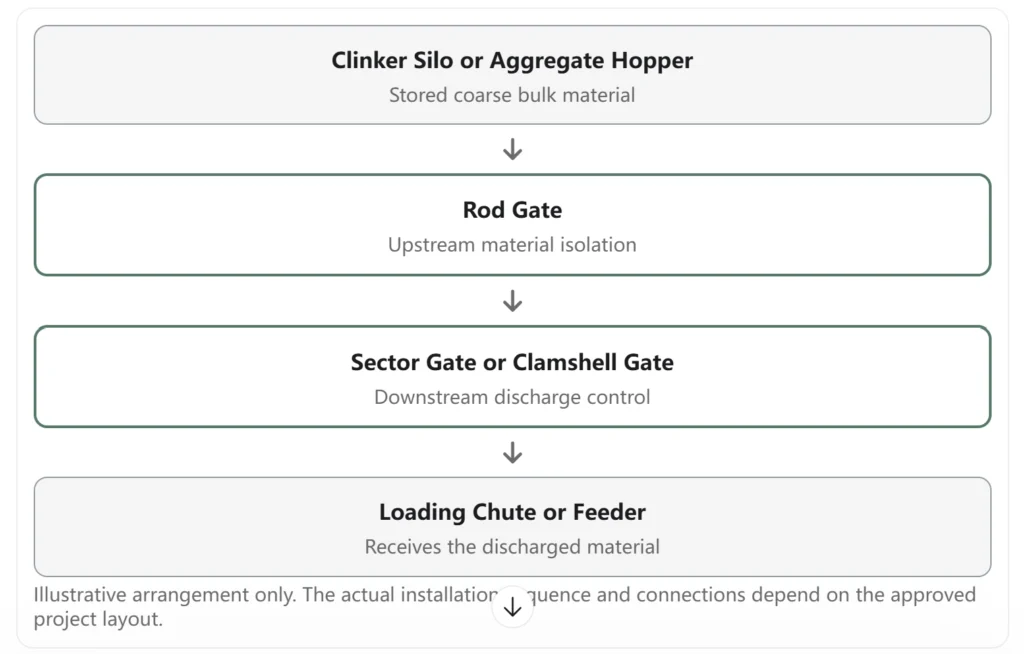
Rod Gate with a Sector Gate
A sector gate uses a single curved blade that rotates around a fixed shaft to open or close the material passage.
When installed downstream of a rod gate, it can be used to control gravity discharge into the connected loading or conveying equipment.
Intermediate opening can provide coarse discharge regulation when supported by the selected actuator and control arrangement.
Rod Gate with a Clamshell Gate
A clamshell gate uses two opposing curved blades synchronized by external gears.
The blades open from opposite sides to form a central discharge passage.
When combined with a rod gate, the two devices perform different functions: the rod gate provides upstream material isolation, while the clamshell gate can control material discharge.
The final arrangement should be selected according to material properties, outlet dimensions, operating requirements and available installation space.
Rod Gate Applications in Clinker Silos and Aggregate Hoppers
Clinker Silo Discharge
In cement plants, clinker is commonly stored in silos or bunkers before being transferred to downstream handling equipment.
A rod gate can be installed at the discharge outlet to isolate the stored clinker from the equipment below.
When combined with an appropriate discharge gate, the arrangement can separate material isolation from the required gravity-discharge operation.
The design must account for clinker lump size, material load, outlet dimensions and the space available for rod withdrawal.
Aggregate Hopper Discharge
Aggregate hoppers may handle gravel, crushed stone and other coarse bulk materials with varying particle sizes.
Rod gates can provide material isolation at the hopper outlet, while a sector gate or clamshell gate can control discharge to a feeder, chute or connected handling equipment.
The installation should be evaluated according to the maximum particle size, outlet geometry, available clearance and downstream equipment.
Limestone and Other Coarse Bulk Materials
Similar arrangements can be considered for limestone bunkers and other coarse bulk material storage facilities.
Material suitability and equipment dimensions must be confirmed for each application.
Installation Considerations for Hopper Discharge Systems
Installing a rod gate for hopper discharge requires checking more than the nominal outlet size, including connection dimensions, withdrawal clearance and downstream equipment.
Engineers should consider the relationship between the rod gate, accompanying discharge gate, surrounding structures and downstream handling equipment.
Hopper Outlet and Connection Dimensions
The rod gate frame must be compatible with the actual hopper outlet.
When a sector gate or clamshell gate is installed downstream, the connection dimensions and total installation height of the combined equipment should be checked.
Existing flange dimensions, structural supports and maintenance access may affect the final arrangement.
Rod Withdrawal Clearance
Sufficient space must be available for rod movement and inspection.
Single-direction and double-direction arrangements have different clearance requirements.
Nearby platforms, structural columns, piping and other equipment should be considered when preparing the installation layout.
For detailed guidance on selecting the appropriate configuration, see our Rod Gate Selection Guide.
Material Load and Operating Conditions
The gate must be designed for the expected bulk material load and operating conditions.
Important factors include maximum lump size, bulk density, material-column height, abrasiveness and operating frequency.
Rod dimensions, supports and drive capacity should be confirmed according to the approved engineering design.
Downstream Equipment Compatibility
The rod gate and accompanying discharge gate should be evaluated together.
Connection dimensions, discharge direction, available installation height and operating access should be checked against the downstream loading chute or feeder.
The final system arrangement must provide suitable interfaces for each device.
Operating and Inspection Considerations
During operation, the rod gate and accompanying discharge gate should follow the operating sequence established for the actual installation.
Inspection should focus on rod movement, material accumulation around the outlet, structural condition and the operating performance of the associated discharge equipment.
Maintenance access must be considered during system design.
Before servicing the equipment, personnel must follow the site’s approved hazardous-energy isolation and material-control procedures. Closing the rod gate alone must not be treated as a substitute for an approved safety isolation procedure. For U.S. facilities, refer to OSHA’s lockout/tagout guidance for additional information on controlling hazardous energy during equipment servicing and maintenance.

FAQs About Rod Gate for Hopper
What is a rod gate for hopper discharge used for?
A rod gate provides material isolation at hopper and silo outlets handling coarse or lumpy bulk solids. Its parallel steel rods can be withdrawn to open the discharge passage. It is commonly used for clinker, aggregates and similar materials.
Where is a rod gate installed in a hopper discharge system?
A rod gate is typically installed at the hopper or silo outlet. In a combined arrangement, it can be positioned upstream of a sector gate or clamshell gate. The actual equipment sequence depends on the approved system design.
Why are rod gates combined with sector gates or clamshell gates?
The devices perform different functions. The rod gate provides material isolation, while the accompanying discharge gate can control material release into downstream equipment.
Can a rod gate control clinker discharge accurately?
A rod gate is primarily an isolation device rather than a precision flow-control gate. Where coarse discharge regulation is required, an appropriate sector gate or clamshell gate can be used. Precise material dosing requires suitable feeding or weighing equipment.
Can rod gates handle large clinker lumps and coarse aggregates?
They can be designed for suitable coarse and lumpy materials. Maximum lump size, bulk density, material load and outlet dimensions must be confirmed before selecting the rod arrangement.
What information is needed when planning a combined hopper discharge arrangement?
Engineers should confirm the material properties, outlet dimensions, available installation space, required operating method, accompanying discharge gate and downstream equipment interfaces. Existing installation drawings are particularly useful.
Conclusion
A rod gate for hopper discharge provides material isolation in clinker, aggregate and other coarse bulk material handling systems.
When combined with a sector gate or clamshell gate, it can form part of an arrangement that separates upstream material isolation from downstream discharge control.
Correct equipment selection and installation depend on material characteristics, outlet dimensions, rod-withdrawal clearance and the associated discharge equipment.
Understanding these requirements helps engineers develop suitable silo and hopper discharge arrangements for their specific operating conditions.
Need Help Planning a Rod Gate for Your Hopper?
If you are planning a clinker silo or aggregate hopper discharge arrangement, please provide:
✓ Material type, bulk density and maximum lump size ✓ Hopper or silo outlet dimensions ✓ Available installation and rod-withdrawal space ✓ Required operating method ✓ Accompanying sector gate, clamshell gate or other equipment ✓ Existing installation drawings or site photographs
LVRUI can review your project information and provide technical suggestions for rod gate configuration, connection dimensions and compatibility with the accompanying discharge equipment.
Email: info@lvrui-conveyor.com
WhatsApp / WeChat: +86 18261998937