How to diagnose slow movement, jamming, unstable discharge, leakage, actuator faults and position-feedback problems in dry bulk flow control gates
Introduction
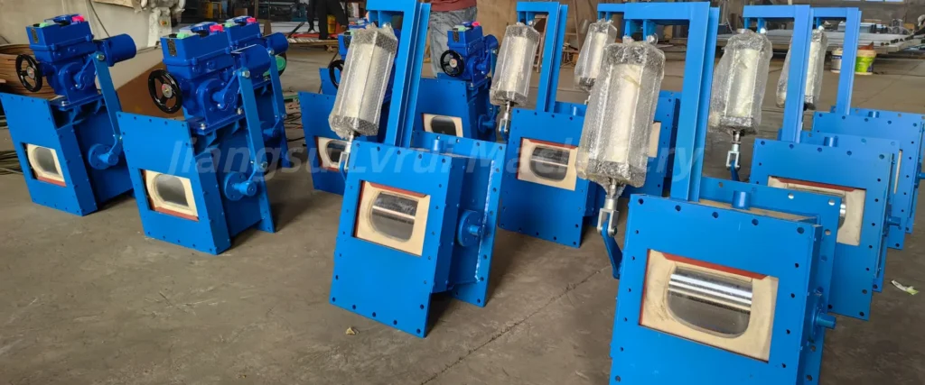
Flow control gate troubleshooting should start by separating mechanical, material-flow, actuator and control-system causes. A gate that moves slowly, becomes jammed, leaks near the closed position or produces unstable discharge is not always suffering from an actuator fault; material buildup, silo-flow conditions, aeration or downstream resistance may be the real cause.
This guide explains practical fault diagnosis for manual, pneumatic and motorized flow control gate valves used below silos, hoppers, air slide systems and other dry bulk handling equipment. The objective is to identify the actual cause before increasing actuator force or replacing components.
Common Flow Control Gate Problems: Quick Diagnostic Checklist
Flow Control Gate Troubleshooting is more effective when symptoms are checked in a systematic order rather than replacing components immediately.
| Symptom | Check First |
|---|---|
| No movement | Power / air supply / interlock |
| Slow movement | Actuator supply / obstruction / friction |
| Stops halfway | Mechanical resistance / actuator force or torque / stroke |
| Cannot fully close | Material trapped / alignment / wear |
| Unstable discharge | Silo flow / aeration / downstream system |
| Position mismatch | Limit switch / sensor / linkage |
| Repeated actuator trip | Overload / obstruction / sizing |
| Excessive leakage | Closing position / clearance / wear |
Before Troubleshooting
Before opening inspection covers, clearing material buildup or working on the gate mechanism, isolate applicable electrical, pneumatic and mechanical energy sources according to the plant’s lockout/tagout procedure and applicable local safety requirements.
Troubleshooting Step-by-Step
1. Gate Does Not Move or Moves Slowly
Possible causes include:
- Insufficient compressed-air pressure for a pneumatic actuator
- Loss of electrical power to a motorized actuator
- Solenoid valve or electrical control fault
- Mechanical obstruction inside the gate
- Misalignment of the gate mechanism
- High material head, compacted powder or material packing creating excessive resistance
- Wear or contamination at guides, bushings, bearings or linkage points, where applicable
- Incorrect interlock or control command
Diagnostic Steps
- Confirm that the actuator has the required power or compressed-air supply.
- Check whether the control command actually reaches the actuator.
- Inspect the gate mechanism for powder buildup or mechanical obstruction.
- Verify that the gate plate, guides, linkage and other moving components can move freely.
- Check limit switches or feedback devices if the control system reports an incorrect position.
- Compare actuator movement with the gate mechanism before replacing electrical or pneumatic components.
2. Excessive Leakage Near the Closed Position
If more material than expected continues to pass when the gate reaches its minimum or intended closed position, first determine whether the problem is mechanical wear, incomplete travel or normal design clearance.
Possible causes include:
- Gate does not reach its mechanical closed position
- Material is trapped between the closing surfaces
- Gate plate, guide, or sealing components are worn
- Actuator stroke is incorrectly adjusted
- Mechanical linkage is loose or misaligned
- Fine powder passes through the normal design clearance
What to Check
First confirm that the gate physically reaches the intended closed position. If it does, inspect the closing surfaces, clearances, guides, and wear condition.
A standard flow control gate should not automatically be treated as a zero-leakage isolation valve. If very low leakage or positive isolation is required, this requirement should be considered separately during equipment selection.
3. Gate Becomes Jammed
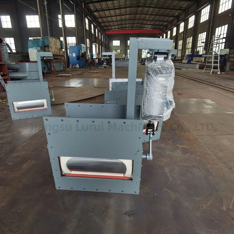
Common causes include:
- Hardened or compacted powder
- Oversized foreign material
- Material buildup around guides or moving parts
- Misalignment
- Worn guide components
- Excessive material load
- Upstream silo-flow problems
Diagnostic Steps
- Stop material discharge safely and isolate applicable electrical, pneumatic, and mechanical energy sources before inspection or clearing a jam. Follow the plant’s safety procedure and applicable local regulations.
- Remove accumulated or foreign material where access permits.
- Check guide alignment and moving clearances.
- Inspect whether the problem originates upstream rather than inside the gate.
- If lumps or compacted material repeatedly reach the gate, evaluate the upstream material condition and whether additional conditioning or lump-breaking equipment is actually required.
4. Powder Discharge Is Unstable
Unstable discharge does not necessarily mean the flow control gate is faulty.
Possible causes include:
- Inconsistent silo aeration
- Material bridging or rat-holing
- Changing material head
- Powder moisture or flowability changes
- Downstream air slide or conveyor instability
- Gate-position fluctuations
- Incorrect actuator or control-loop response
Before adjusting the gate repeatedly, verify whether the material above and below the gate is flowing consistently.
The flow control gate changes the discharge opening, but it cannot compensate for every upstream silo-flow problem.
When unstable discharge originates from aeration, material flow, or the surrounding silo equipment, the complete cement silo discharge system should be checked rather than adjusting the gate alone.
5. Position Feedback Does Not Match the Actual Gate Position
Possible causes include:
- Misaligned or incorrectly adjusted limit switch
- Loose mechanical coupling between the gate and feedback device
- Linkage backlash or mechanical play
- Incorrect sensor or positioner calibration
- Wiring or control-signal fault
- Incorrect PLC/HMI signal scaling
- The gate is mechanically obstructed and does not actually reach the commanded position
Diagnostic Steps
- Compare the actual physical gate position with the position shown on the PLC, HMI or local indicator.
- Inspect the mechanical connection between the gate mechanism and the feedback device.
- Check limit-switch or sensor alignment and mounting.
- Verify wiring, signal range and control-system scaling.
- Confirm that the gate can physically reach the commanded position without abnormal resistance.
Do not correct a position mismatch only by recalibrating the feedback signal if the gate mechanism itself is restricted or misaligned.
Actuator-Specific Checks
For pneumatic gates, check compressed-air pressure, solenoid valves, cylinder leakage, tubing and end-position sensors. For actuator sequencing, positioning and control logic, see our Pneumatic Flow Control Gate Working Principle guide.
For motorized gates, check power supply, actuator fault signals, torque protection, limit switches, linkage, and position feedback. For electric actuator configuration, feedback, and PLC control, see Motorized Flow Control Gate Actuator.
For detailed drive-type differences, see Pneumatic vs Electric Flow Control Gate Valve.
Preventive Maintenance to Reduce Flow Control Gate Failures
Preventive maintenance makes flow control gate troubleshooting easier by identifying wear, material buildup and actuator problems before they develop into repeated failures.
Check:
✓ Gate movement and travel
✓ Guide and sliding surfaces
✓ Mechanical alignment
✓ Fasteners and linkage
✓ Pneumatic tubing and cylinder condition
✓ Motorized actuator fault history
✓ Limit switches and position sensors
✓ Material buildup around moving parts
✓ Wear at closing and guide surfaces
Inspection frequency should be based on operating cycles, material abrasiveness, dust conditions, and the consequences of gate failure.
FAQs About Flow Control Gate Troubleshooting
Why is my flow control gate moving slowly?
Slow movement may come from insufficient actuator supply, mechanical resistance, material buildup, misalignment, or a control fault. Check the mechanical and actuator sides separately.
Why does the gate stop before fully opening or closing?
Common causes include incorrect actuator stroke, excessive resistance, obstruction, misalignment, or incorrect limit settings.
Can increasing pneumatic pressure solve a sticking gate?
Not necessarily. The cause should first be identified. Increasing pressure cannot correct mechanical misalignment, material obstruction, or worn components.
Why is powder discharge unstable even when the gate position is unchanged?
Material flow may change because of silo head, aeration, bridging, powder properties, or downstream resistance.
Does a closed flow control gate provide zero leakage?
Not necessarily. Leakage depends on gate design, clearance, wear, material characteristics, and operating conditions.
Can a flow control gate be used as a positive shut-off valve?
Not automatically. A flow control gate is primarily intended to adjust material discharge by changing the opening position. If positive isolation or very low leakage is required, the isolation requirement should be specified separately and a dedicated shut-off valve or suitable isolation gate may be required.
Conclusion
Flow control gate troubleshooting should start with the complete discharge system rather than the actuator alone. Slow movement, jamming, unstable powder discharge, leakage, and position errors may originate from mechanical wear, material condition, actuator performance, control signals, or upstream and downstream equipment.
A systematic diagnosis should separate these possible causes before components are replaced or operating force is increased. Regular inspection of the gate mechanism, actuator, feedback devices, and surrounding material-flow conditions can reduce unexpected downtime and make maintenance more predictable.
Need Help Diagnosing a Flow Control Gate Problem?
If your flow control gate is moving slowly, jamming, leaking material, or showing incorrect position feedback, provide:
- Gate type and size
- Manual, pneumatic, or motorized actuation
- Material handled
- Description of the fault
- Current gate position when the fault occurs
- Available air pressure or electrical supply
- Photos or video of the gate and actuator
- Silo / hopper / downstream equipment layout
LVRUI can review the operating condition and help identify whether the problem is more likely related to the gate mechanism, actuator, control system, or surrounding material-flow conditions.
Email: info@lvrui-conveyor.com
WhatsApp / WeChat: +86-18261998937