How electric actuators, torque, limit switches, position feedback and PLC control work together in dry bulk powder discharge systems
What Does the Motorized Actuator Actually Control?
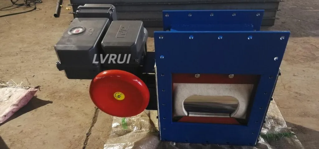
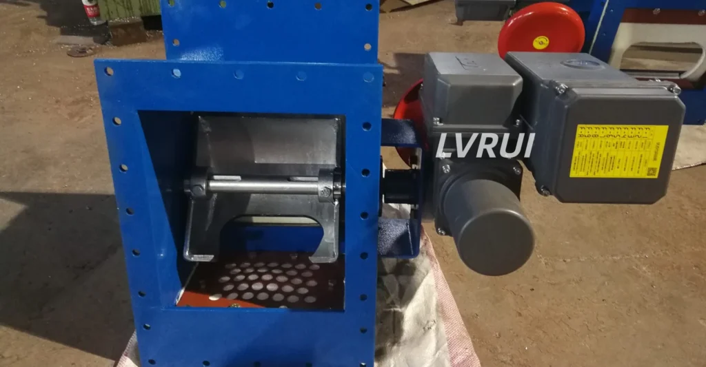
A motorized flow control gate actuator provides the mechanical movement required to position the gate opening below a silo or hopper. Depending on the control configuration, it may support open-close operation, intermediate positioning, local control, remote commands, or PLC integration.
The actuator positions the gate opening but does not directly measure or determine the material mass flow rate. Its function is to position the gate opening according to a local command, remote signal, or PLC control logic.
The actual powder discharge rate still depends on operating conditions such as:
✓ Material bulk density
✓ Flowability
✓ Silo head
✓ Aeration condition
✓ Gate opening
✓ Downstream resistance
This distinction is important because a repeatable gate position does not automatically mean a fixed or precisely measured material flow rate.
Main Components of a Motorized Control System
Electric Actuator
Provides the mechanical torque required to move the gate to the commanded position.
Gearbox or Transmission
Transfers actuator output to the gate mechanism and affects operating speed and available torque.
Limit Switches
Confirm fully open and fully closed positions and can be used for control interlocks.
Position Feedback
A potentiometer, encoder, or other position transmitter can provide intermediate-position feedback where required by the control system.
Local Control
Allows operation from a nearby panel or local station for commissioning, inspection, or maintenance.
PLC or DCS Interface
Allows remote commands, interlocks, position monitoring, and automatic sequence control.
Open-Close Control vs Intermediate Positioning
Motorized flow control gates may be configured for simple open-close operation or for adjustable intermediate positioning.
Open-Close Operation
Suitable where the gate is mainly used to start or stop material discharge between defined operating states.
Intermediate Positioning
Used where the gate opening must be adjusted to match downstream process requirements.
Intermediate positioning requires more than simply installing an electric motor. The actuator and control system should support:
✓ Repeatable positioning
✓ Suitable travel control
✓ Position feedback where required
✓ Stable holding at intermediate positions
✓ Compatible PLC or local control signals
The gate opening can influence discharge rate, but it should not be treated as a calibrated mass-flow measurement unless the complete system includes suitable feedback or metering equipment.
How to Select Actuator Torque
Motorized flow control gate actuator torque should not be selected from gate size alone. The required torque depends on the gate structure, transmission arrangement, material load, friction, operating conditions, and required safety margin.
The required torque can be influenced by:
✓ Gate dimensions
✓ Mechanical transmission ratio
✓ Material load on the gate element
✓ Friction in guides and seals
✓ Dust accumulation
✓ Operating temperature
✓ Required safety margin
✓ Opening and closing speed
An undersized actuator may stall or fail to reach the commanded position. An unnecessarily oversized actuator can increase cost and may place additional mechanical load on the transmission components.
Final torque selection should therefore be based on the actual valve structure and operating conditions rather than a generic size-to-torque rule.
Power Supply, Speed and Duty Cycle
Before confirming the electric actuator, verify:
Power Supply
Confirm available voltage, frequency, phase, and site electrical standards.
Operating Speed
Faster travel is not automatically better. Required speed depends on process response, downstream equipment, and control sequence.
Duty Cycle
Frequent repositioning may require an actuator designed for higher operating frequency than an actuator used only occasionally.
Ambient Conditions
Dust, temperature, humidity, and enclosure requirements should match the installation environment.
Position Feedback and Limit Switches
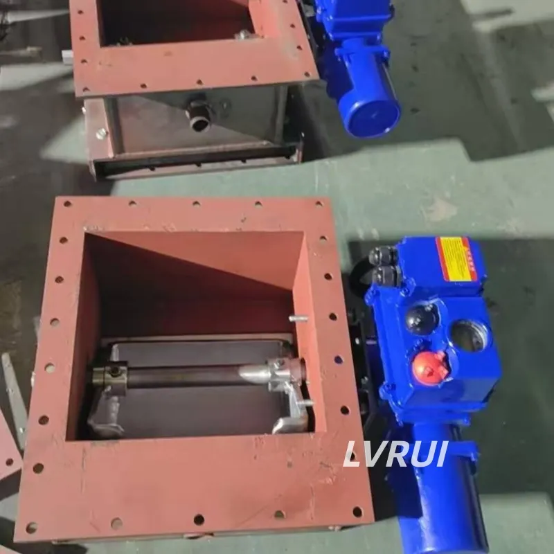
Limit switches and position feedback serve different purposes.
Limit switches normally confirm end positions such as fully open and fully closed.
Position feedback provides information about intermediate gate position and can support remote monitoring or automatic control.
Depending on project requirements, the system may use:
✓ Open limit signal
✓ Closed limit signal
✓ Intermediate position signal
✓ 4–20 mA position feedback
✓ Digital or fieldbus communication
✓ Local position indication
Depending on the actuator configuration, electric actuator systems may support analogue position feedback, status signals, intermediate positions, and fieldbus communication. For an industry reference on these control interfaces, see the AUMA actuator control interface.
PLC Control Logic for a Motorized Flow Control Gate
A motorized flow control gate can be integrated into a PLC-controlled silo discharge sequence.
Typical control logic may include:
- Confirm downstream equipment is ready.
- Confirm required interlocks are satisfied.
- Command the gate to open or move to a defined position.
- Verify gate position through limit switches or feedback.
- Monitor downstream process condition.
- Adjust or close the gate when required.
- Generate an alarm if commanded movement is not confirmed within the expected time.
The actual sequence depends on the plant process and should be defined by the system integrator or control engineer.
Common Control Problems
Gate Does Not Move
Check power supply, actuator protection, mechanical obstruction, transmission condition, and interlocks.
Gate Stops Before Reaching Position
Check torque setting, mechanical resistance, limit settings, and possible material buildup.
Position Feedback Does Not Match Actual Gate Position
Inspect feedback calibration, coupling, linkage, wiring, and control scaling.
Frequent Actuator Trips
Check actuator sizing, operating frequency, thermal protection, abnormal resistance, and duty-cycle suitability.
PLC Command Is Present but No Movement Occurs
Confirm local/remote selector position, interlocks, actuator availability, control wiring, and fault signals.
For mechanical movement, sealing, material buildup, and other general gate faults, see our Flow Control Gate Troubleshooting guide.
Motorized Gate vs Pneumatic Gate in Control Systems
Motorized actuation is often preferred where electrical control, stable intermediate positioning, and operation without compressed air are required.
Pneumatic actuation is often preferred where fast response and frequent operation are required and plant compressed air is available.
Both can be integrated into automated systems when configured with appropriate feedback and control components.
For complete drive-type selection, see the Flow Control Gate Selection Guide.
For pneumatic actuation configurations and product details, see our Pneumatic Flow Control Gate page.
When This Control Configuration Is Suitable
✓ Silo discharge requiring remote electrical operation
✓ PLC-controlled cement or fly ash discharge
✓ Applications requiring intermediate gate positions
✓ Locations without convenient compressed-air supply
✓ Systems requiring gate position confirmation
✓ Automated loading or conveying sequences
For manual, pneumatic, and motorized configurations across dry bulk applications, see our Flow Control Gate Valve product range.
FAQs About Motorized Flow Control Gate Actuator
What controls the position of a motorized flow control gate?
An electric or geared actuator moves the gate mechanism to the commanded position.
Does gate position directly indicate material flow rate?
No. Gate position affects the discharge opening, but actual material flow also depends on material properties, silo head, aeration, and downstream resistance.
What is the difference between limit switches and position feedback?
Limit switches normally confirm end positions, while position feedback can provide information about intermediate gate position.
Can a motorized flow control gate be controlled by a PLC?
Yes, when the actuator and control system are configured for remote commands, interlocks, and required feedback signals.
How is actuator torque selected?
Torque should be selected according to valve structure, material load, friction, operating conditions, required speed, and a suitable engineering margin.
Is a motorized flow control gate suitable for precise dosing?
Not by itself. Accurate dosing normally requires suitable weighing, metering, or process feedback in addition to the gate.
Conclusion
A motorized flow control gate actuator is only one part of the complete automated discharge control arrangement. Reliable operation also depends on travel limits, operating speed, duty cycle, position feedback, interlocks, and PLC control logic.
The actuator positions the gate opening, while the actual material discharge rate is still influenced by powder properties, silo conditions, and downstream resistance. For this reason, motorized gate control should be designed around the process requirements rather than assuming that a specific opening position directly represents a fixed mass flow.
Need Help Configuring a Motorized Flow Control Gate Control System?
If you are evaluating a motorized flow control gate for cement, fly ash, raw meal, or other dry powders, provide:
- Material name and bulk density
- Silo or hopper outlet size
- Required operating mode
- Power supply
- Required opening speed
- PLC or local control requirement
- Position feedback requirement
- Operating frequency
- Downstream equipment
LVRUI can review the operating conditions and help determine the suitable gate configuration, electric actuator, torque range, feedback arrangement, and control interface.
Email: info@lvrui-conveyor.com
WhatsApp / WeChat: +86-18261998937