A Practical Layout Selection Guide for Cement Silo Tanker Loading
Quick Answer
The correct cement bulk loader layout depends on the silo outlet position, tanker access, available headroom and powder conveying route.
Choose an under-silo cement bulk loader when the tanker can park directly below the silo outlet and sufficient vertical clearance is available.
Choose a side-silo cement bulk loader when the truck lane cannot pass beneath the silo, the loading point must be separated from the storage area, or the plant requires more flexible vehicle access.
The correct layout is not determined by loading capacity alone. Silo position, truck route, available headroom, upstream conveying equipment, dust collection and future maintenance access must be evaluated together.
What Is an Under-Silo Cement Bulk Loader?
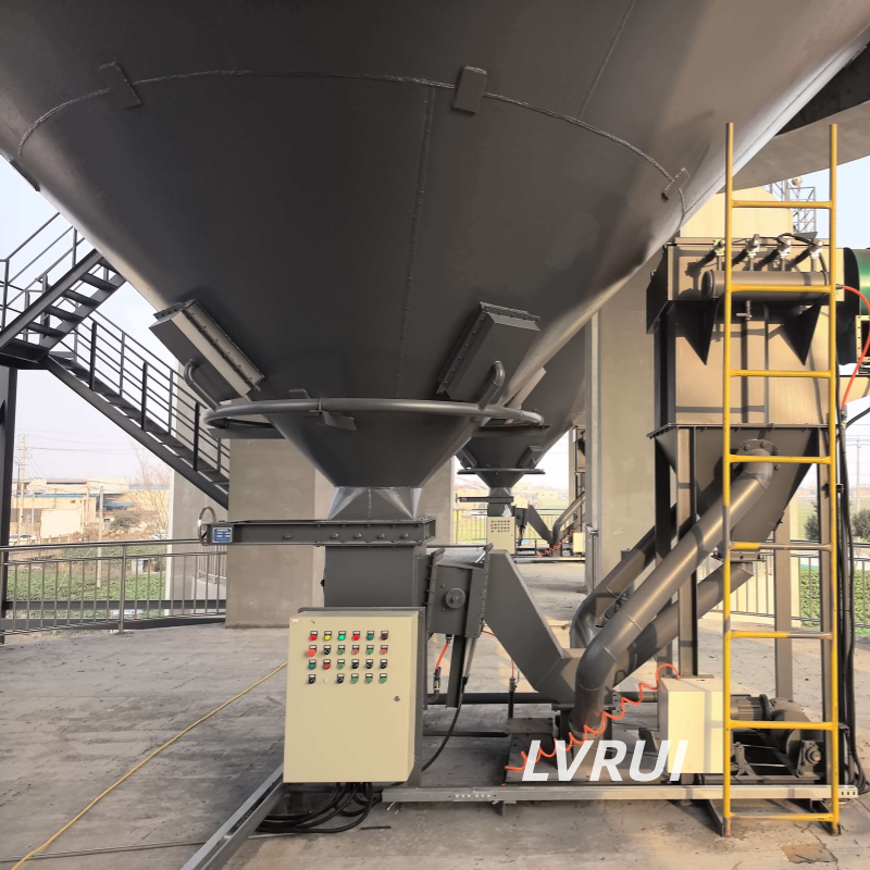
An under-silo cement bulk loader is installed directly below the discharge outlet of a cement, fly ash or fine-powder storage silo.
During loading, material moves downward from the silo through the discharge and flow-control equipment before entering the tanker through the loading head. Because the material path is short and mainly gravity-assisted, this arrangement usually requires fewer transfer components.
A typical under-silo arrangement may include:
✓ Silo outlet
✓ Manual slide gate or maintenance isolation gate
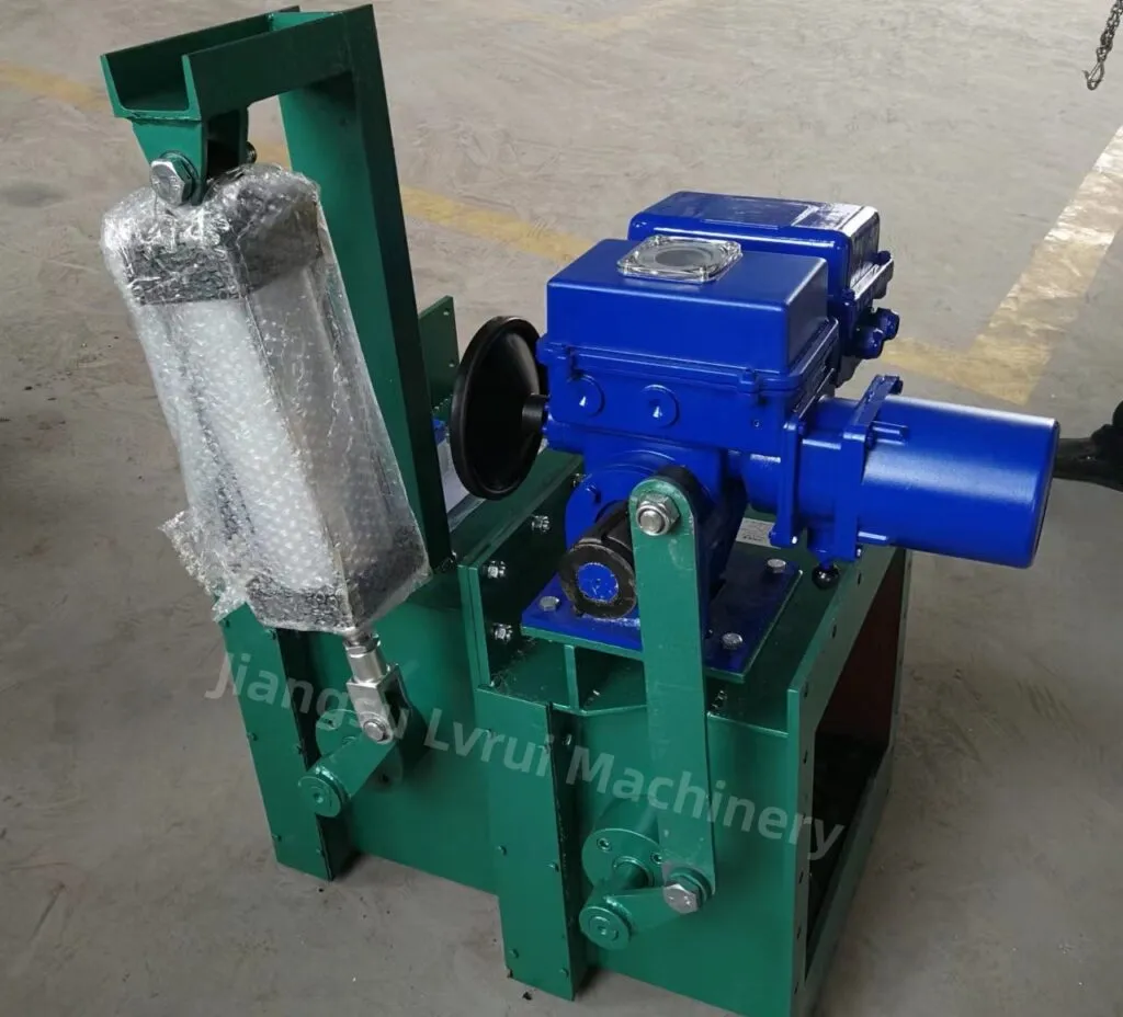
✓ Flow control gate
✓ Pneumatic on-off valve, depending on the system
✓ Cement bulk loader
✓ Level detection or loading-stop signal
✓ Integrated or external dust collection connection
This layout is most practical when the tanker can enter the space below the silo safely and align its inlet with the loading head.
Main Advantages of an Under-Silo Layout
✓ Short material flow path
✓ Fewer intermediate conveying components
✓ Compact system arrangement
✓ Direct connection with the silo outlet
✓ Lower risk of transfer-point leakage
✓ Simpler control sequence in many projects
However, the apparent simplicity can be misleading. The silo must have enough ground clearance, and the truck lane must allow safe entry, alignment and exit without interfering with silo supports or other equipment.
What Is a Side-Silo Cement Bulk Loader?
A side-silo cement bulk loader is installed beside the storage silo rather than directly below it.
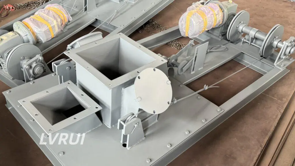
Material first discharges from the silo and then moves to the loading point through an air slide conveyor, screw conveyor or another suitable transfer device. The tanker parks at a separate loading bay next to the silo.
A typical side-silo arrangement may include:
✓ Silo discharge and aeration equipment
✓ Isolation and flow-control gates
✓ Air slide conveyor or screw conveyor
✓ Transfer chute or connection section
✓ Side-mounted cement bulk loader
✓ Level sensor or external weighing signal
✓ Dust collection and control system
The side-silo layout is more suitable when the structural columns, limited headroom, existing buildings or traffic route prevent the tanker from entering directly below the silo.
Main Advantages of a Side-Silo Layout
✓ More flexible tanker positioning
✓ Loading bay can be separated from the silo foundation
✓ Easier adaptation to restricted truck routes
✓ Maintenance can be arranged away from the silo centre
✓ Multiple silos may feed a shared loading point
✓ Suitable for renovation projects with limited under-silo space
The trade-off is that the side-silo arrangement normally requires additional conveying equipment, transfer connections and control interlocks.
Under-Silo vs Side-Silo Cement Bulk Loader Comparison
The following comparison shows how each cement bulk loader layout affects tanker positioning, material transfer, equipment quantity and maintenance access.
| Selection Factor | Under-Silo Layout | Side-Silo Layout |
|---|---|---|
| Installation Position | Directly below the silo outlet | Beside or away from the silo |
| Material Route | Short, mainly vertical | Includes horizontal or inclined transfer |
| Tanker Position | Directly under the silo | At a separate loading bay |
| Transfer Equipment | Usually limited | Air slide or screw conveyor commonly required |
| Required Headroom | Sufficient clearance below the silo | More flexible loading-point elevation |
| Truck Access | Depends on silo columns and foundation | Easier to adapt to the plant traffic route |
| System Complexity | Generally simpler | More components and interlocks |
| Maintenance Access | May be restricted below the silo | Can be arranged more openly |
| Expansion Potential | Usually dedicated to one silo | Can connect multiple silos to one loading point |
| Typical Use | New silos with planned tanker access | Existing plants, restricted sites or shared loading bays |
Neither layout is automatically better. The correct solution is the one that provides stable powder feeding, safe tanker access, adequate dust control and practical maintenance space.
Safe tanker access should also follow recognized loading-area practices. The UK Health and Safety Executive recommends locating loading areas where vehicles can manoeuvre safely and separating loading operations from unrelated traffic and pedestrians.
Six Factors That Determine the Correct Layout
1. Silo Outlet Position
The first question is whether the silo outlet is located directly above a usable truck lane.
For a new project, the silo foundation and vehicle route can be designed around an under-silo loader. For an existing plant, columns, platforms, pipework or nearby buildings may make direct tanker access impossible.
Do not select the loader position from the silo drawing alone. The complete lower-silo structure must be reviewed.
2. Tanker Access and Turning Route
A tanker needs more than a space directly below the loading head. The plant must also provide:
✓ Safe approach and exit route
✓ Sufficient turning radius
✓ Clearance from silo columns
✓ Driver visibility or positioning assistance
✓ Space for hoses, platforms and maintenance work
✓ Protection from collisions with the loading equipment
When these conditions cannot be achieved below the silo, a side-silo loading bay is normally more practical.
3. Available Loading Height
The loader must reach the tanker inlet while maintaining enough retracted clearance for vehicle movement.
Important dimensions include:
✓ Height from the mounting flange to ground level
✓ Tanker inlet height
✓ Required loading-head travel
✓ Retracted loader height
✓ Silo outlet and valve installation height
✓ Allowance for flexible connections and maintenance
Insufficient vertical clearance is one of the most common reasons an under-silo concept becomes difficult to implement.
4. Material Transfer Route
An under-silo loader receives material over a short vertical path. A side-silo loader requires the powder to travel from the silo outlet to the separate loading point.
For dry, fine and fluidizable powders, an air slide conveyor may provide enclosed, low-wear transfer where sufficient slope is available.
A screw conveyor may be considered where the route, elevation or installation constraints do not suit an air slide. However, its capacity, inlet feeding and wear conditions must be checked carefully.
The transfer equipment must be sized for the required loading rate. A high-capacity loader cannot compensate for an undersized upstream conveyor.
5. Dust Collection Arrangement
Dust control depends on more than the loading head itself.
The system may use:
✓ An integrated filter on the cement bulk loader
✓ A separate bag filter
✓ A dust-return duct connected to a centralized collector
✓ A sealed tanker connection
✓ Level detection to reduce overfilling risk
✓ Interlocking between feeding and dust extraction
An under-silo arrangement may have a shorter dust-return path, while a side-silo loading station can provide more space for a separate dust collector.
Actual dust-control performance depends on sealing, extraction airflow, filter capacity, tanker connection and operating procedure. The correct objective is dust-controlled loading, not an unsupported promise of completely dust-free operation.
6. Maintenance and Future Expansion
The loader, flow-control gate, level sensor, flexible parts and dust collection components require inspection and maintenance.
Check whether technicians can safely access:
✓ The loading head
✓ Hoist or lifting mechanism
✓ Flow-control equipment
✓ Flexible shroud or sealing parts
✓ Level sensor
✓ Dust filter
✓ Transfer conveyor
✓ Inspection openings
A side-silo layout often provides easier access, but it also creates more components requiring maintenance. An under-silo system has fewer transfer parts, but the working area beneath the silo may be restricted.
Future expansion should also be considered. A shared side-silo loading bay may be useful when several storage silos need to feed the same tanker loading point.
Typical Equipment Configuration
Under-Silo Cement Bulk Loader
A typical material route is:
Silo → isolation gate → flow control gate → cement bulk loader → tanker
Depending on the project, the system can also include:
✓ Silo aeration equipment
✓ Lump-breaking equipment where caking is possible
✓ Pneumatic on-off valve
✓ Integrated dust collector
✓ High-level sensor
✓ External weighing interlock
✓ PLC control cabinet
The flow control gate regulates the discharge rate. It should not be treated as the only solution for silo bridging or poor powder flow.
Side-Silo Cement Bulk Loader
A typical material route is:
Silo → discharge equipment → flow control gate → air slide or screw conveyor → cement bulk loader → tanker
This configuration requires coordination between:
✓ Silo discharge rate
✓ Conveyor capacity
✓ Loading-head capacity
✓ Dust extraction
✓ Level detection
✓ Start-and-stop sequence
The transfer conveyor should start before material feeding begins. At the end of loading, the control sequence should allow the conveyor and loading head to clear safely before shutdown.
Where the project includes coordinated upstream feeding, flow control, dust extraction, level detection and electrical interlocks, see our complete Bulk Loading System configuration.
Common Cement Bulk Loader Layout Mistakes
Selecting the Loader Before Checking the Truck Route
A technically suitable loader can still fail as a project solution if the tanker cannot approach, align or leave safely.
Ignoring the Retracted Height
The extended loading length is important, but the retracted height determines whether the tanker can enter and exit without hitting the loading head.
Using a Side-Silo Layout Without Checking Conveyor Capacity
The side-mounted loader may be rated for a high loading capacity, but the actual output will be limited by the silo discharge and upstream conveyor.
Relying on the Flow-Control Gate to Solve Silo Blockage
Unstable discharge may be caused by insufficient aeration, moisture, material compaction, undersized outlets or hardened lumps. A flow-control gate regulates material flow but does not correct every silo-flow problem.
Treating Dust Collection as an Optional Final Addition
The dust collector, return-air path and sealing structure should be planned with the loader layout. Adding an undersized filter after installation often leads to poor capture performance.
Using a Cement Powder Loader for Clinker
A standard cement bulk loader is intended for cement, fly ash, lime powder, slag powder and similar fine dry materials.
Granular and abrasive clinker requires a dedicated clinker bulk loader with a different outlet, wear-resistant structure and material-flow design.
Which Layout Is More Suitable for Your Plant?
Choose an under-silo cement bulk loader when:
✓ The tanker can park directly below the silo
✓ The silo has sufficient ground clearance
✓ A compact material route is preferred
✓ The system serves one main loading outlet
✓ Minimal transfer equipment is required
Choose a side-silo cement bulk loader when:
✓ Silo columns prevent direct tanker access
✓ The loading bay must be separated from the silo
✓ Existing plant layout limits under-silo installation
✓ Several silos may feed one loading point
✓ Maintenance access is easier beside the silo
✓ An existing air slide or screw conveyor can feed the loader
For many new cement silos, the under-silo layout is the simpler option. For plant renovations and restricted sites, the side-silo layout is often more adaptable.
Information Required for Cement Bulk Loader Selection
Selecting the correct cement bulk loader layout requires accurate silo dimensions, tanker information and a general arrangement drawing.
To compare the two layouts accurately, provide:
✓ Material name and bulk density
✓ Required loading capacity
✓ Silo outlet dimensions
✓ Silo outlet height above ground
✓ Tanker inlet diameter and height
✓ Available loading-head travel
✓ Truck approach and exit direction
✓ Existing air slide or screw conveyor details
✓ Dust collection arrangement
✓ Required level detection or weighing interlock
✓ General arrangement drawing or site photographs
A layout drawing is more useful than a loading-capacity figure alone. It allows the loader position, transfer route, headroom and maintenance space to be reviewed together.
FAQs About Under-Silo and Side-Silo Cement Bulk Loaders
What is the main difference between an under-silo and side-silo cement bulk loader?
An under-silo loader is installed directly below the silo outlet. A side-silo loader is installed at a separate loading point and requires conveying equipment to transfer powder from the silo to the loader.
Is an under-silo cement bulk loader always more economical?
Not necessarily. It usually requires fewer transfer components, but it may require major silo-foundation or vehicle-route changes. In an existing plant, a side-silo layout may be more economical if direct tanker access is not available.
What conveyor is used for a side-silo cement bulk loader?
An air slide conveyor is commonly used for dry, fine and fluidizable powders where sufficient slope is available. A screw conveyor may be selected for other layouts. The correct choice depends on material properties, distance, elevation and required capacity.
Can several silos connect to one side-silo loading station?
Yes, provided the feeding routes, gates, conveying equipment and control logic are designed to prevent cross-flow and incorrect material selection. Each silo connection must be evaluated individually.
How is cement tanker overfilling controlled?
Loading can be stopped by a tanker high-level sensor, external weighing signal or plant control-system interlock. The selected method depends on the loader configuration and the customer’s operating procedure.
What materials are suitable for a cement bulk loader?
A cement bulk loader is suitable for cement, fly ash, lime powder, slag powder, limestone powder and similar fine dry materials. Material flowability, temperature, moisture and bulk density should be confirmed before selection. Granular clinker requires a separate clinker-loading design.
Conclusion
The main difference between an under-silo and side-silo cement bulk loader is the relationship between the silo outlet and the tanker loading bay.
An under-silo layout provides a shorter and generally simpler material route when sufficient clearance and truck access are available. A side-silo layout provides greater flexibility where the plant structure, vehicle route or maintenance requirements prevent direct loading below the silo.
The final decision should be based on the complete plant layout—not only the loader capacity or purchase price.
The best cement bulk loader layout is the one that provides stable feeding, safe tanker access, effective dust control and practical maintenance space.
Need Help Comparing Under-Silo and Side-Silo Layouts?
Send LVRUI your material name, required loading capacity, silo outlet dimensions, silo outlet height, tanker inlet dimensions, truck access direction and available site layout or photos.
Based on this information, LVRUI can evaluate whether an under-silo or side-silo cement bulk loader arrangement is more suitable and review the required loading height, material transfer route, dust-control interfaces and preliminary equipment configuration.
Email: info@lvrui-conveyor.com
WhatsApp: +86-18261998937
WeChat: +86-18261998937