Six practical causes of material cross-flow in cement, clinker and bulk material handling systems
Quick Answer: What Causes Y Type Diverter Valve Leakage?
Y type diverter valve leakage usually means that the internal flap does not completely block the inactive outlet.
The most common causes are:
- The actuator does not complete its full stroke
- Material is trapped around the flap
- The flap, shaft, bushings or liners are worn
- The valve switches while material is still flowing heavily
- Oversized particles or foreign objects jam the flap
- Installation errors or downstream blockage affect the valve
A small amount of material falling immediately after switching may be residual material inside the valve body or chute. Continuous material flow into the closed outlet indicates that the flap is not sealing or positioning correctly.
Residual Material or Continuous Internal Leakage?
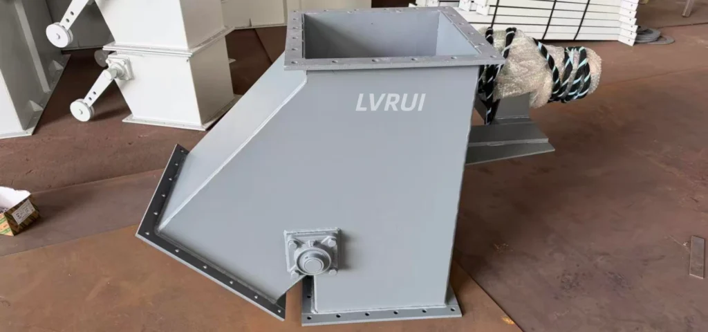
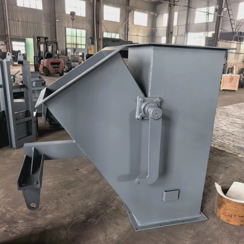
A Y type diverter valve has one inlet and two downstream outlets. Its internal flap changes position to direct cement powder, clinker, granules or other bulk material toward the selected branch.
After switching, a small amount of material may remain:
- Inside the central valve chamber
- On the flap surface
- In the outlet transition
- Inside the downstream chute
This residual material may continue falling for a few seconds.
Residual discharge is generally normal when:
- The amount is small
- It occurs only after switching
- The discharge stops quickly
- No further material enters the inactive outlet
The condition should be treated as internal leakage when:
- Material continuously enters the closed outlet
- Both outlets receive material simultaneously
- Leakage increases at higher flow rates
- The problem becomes worse over time
- The inactive outlet receives material throughout operation
This distinction prevents unnecessary replacement of a valve that is only releasing material left inside its chamber.
Main Causes of Y Type Diverter Valve Leakage
1. The Actuator Does Not Complete Its Full Stroke
Incomplete actuator travel is one of the most common causes of leakage into the closed outlet.
The actuator may appear to finish its switching cycle while the internal flap remains slightly away from the required end position.
Possible causes include:
- Incorrect pneumatic cylinder stroke
- Low compressed-air pressure
- Insufficient electric actuator travel
- Loose linkage between the actuator and shaft
- Incorrect mechanical stop position
- Limit switches activated too early
- Worn or deformed connecting parts
Even a small opening can allow cement powder, clinker particles or granules to enter the inactive branch.
Do not rely only on the PLC display. The control system may indicate that Outlet A has been selected while the flap has not completely closed Outlet B.
The inspection should compare:
- Actual flap position
- Shaft rotation angle
- Actuator travel
- Mechanical stop position
- Limit-switch signal
- Air pressure or actuator torque
Position confirmation should represent the real mechanical end position, not just the actuator command.
2. Material Buildup Prevents the Flap from Closing
Cement powder, clinker fragments, dust or sticky material may accumulate around the flap edge or internal seating area.
Common buildup locations include:
- Flap edges
- Internal corners
- Shaft penetration points
- Lower valve body
- Outlet transitions
- Liner joints
Fine powder can compact into narrow gaps. Coarse particles may become trapped between the flap and the valve body. Moist or partially hardened material can create a more serious obstruction.
Typical signs include:
- Switching time becomes longer
- The actuator requires more force
- Scraping or impact noise appears
- Leakage improves temporarily after cleaning
- The problem returns after continuous operation
If buildup occurs repeatedly, inspect the material condition, moisture, particle size, upstream feeding stability and switching sequence.
Cleaning may restore normal operation, but repeated buildup indicates that the operating cause has not been removed.
3. The Flap, Shaft or Internal Liners Are Worn
Diverter valves handling clinker, granules and abrasive bulk materials are exposed to continuous impact and sliding wear.
Over time, wear can increase the clearance between the flap and the internal wall.
Components that should be inspected include:
- Internal flap
- Flap edges
- Wear liners
- Shaft
- Shaft bushings
- Bearings
- Linkage arms
- Mechanical stops
Wear does not always occur evenly. The upper part of the flap may remain in reasonable condition while the lower edge becomes thinner.
Worn shaft bushings may also allow the flap to move sideways. The actuator can complete its stroke while the flap no longer aligns correctly with the inactive branch.
Wear-related leakage normally develops gradually. The valve may operate correctly without material but leak under full flow because the flap shifts under load.
For clinker and other abrasive materials, replaceable wear-resistant liners can extend service life. They do not eliminate the need for periodic inspection.
4. The Valve Switches Under Heavy Material Flow
When the valve changes position while a large quantity of material is pressing against the flap, the material can resist its movement.
Particles may also become trapped between the flap and the valve body during switching.
This can cause:
- Incomplete flap travel
- Actuator overload
- Particle jamming
- Faster internal wear
- Damage to the linkage
- Material entering both outlets
The risk is higher when handling:
- Clinker
- Irregular particles
- Dense bulk solids
- Large granules
- Material discharged directly from a full hopper
Where the process allows it, use the following switching sequence:
- Reduce or stop upstream feeding.
- Allow material inside the valve to discharge.
- Move the flap to the required outlet.
- Confirm the final position.
- Restart normal feeding.
If the material flow cannot be stopped, the actuator output, valve geometry, bulk density, particle size and switching frequency must be considered during equipment selection.
5. Oversized Particles or Foreign Objects Jam the Flap
A valve may handle normal material correctly but still be blocked by occasional oversized pieces. If hardened cement lumps repeatedly enter the valve, a cement silo lump breaker may be installed upstream to reduce oversized material before it reaches the diverter.
Possible obstructions include:
- Large clinker lumps
- Hardened cement blocks
- Metal fragments
- Loose bolts
- Welding slag
- Damaged liner pieces
- Agglomerated material
A trapped object may prevent the flap from fully closing while the actuator or limit switch still indicates that switching is complete.
If leakage occurs mainly with clinker or coarse material, check:
- Maximum particle size
- Valve opening dimensions
- Internal flap clearance
- Frequency of oversized lumps
- Possibility of foreign objects entering the system
Valve size should be selected according to both required capacity and maximum particle size.
A valve may have sufficient theoretical throughput but still jam if its internal clearance is too small for occasional large particles.
6. Installation or Downstream Conditions Are Incorrect
The valve may be mechanically functional while the surrounding installation prevents correct operation.
Possible installation problems include:
- Valve body installed out of alignment
- Inlet or outlet flange mismatch
- Excessive loads from connected chutes
- Uneven flange tightening
- Insufficient valve support
- Outlet transitions smaller than the valve opening
- Downstream material buildup
- A closed or restricted downstream gate
Body deformation can change the clearance between the flap and the valve wall.
Downstream blockage can also cause material to back up into the central chamber. In this case, material observed in the inactive branch may be returning from the outlet rather than passing directly through the flap gap.
Confirm that both outlet branches discharge freely and that the connected chutes do not distort or overload the valve body.
Y Type Diverter Valve Leakage Troubleshooting Table
The symptoms of Y type diverter valve leakage vary depending on whether the cause is mechanical wear, material buildup or incorrect actuator positioning.
| Observed condition | Likely cause | First inspection point |
|---|---|---|
| Material continuously enters both outlets | Flap does not fully reach its end position | Flap position and actuator stroke |
| Leakage begins after several hours | Material buildup | Flap edge and seating area |
| Valve works empty but leaks under full flow | Excessive switching load | Operating sequence and actuator output |
| PLC shows the correct outlet but leakage continues | Feedback does not match the mechanical position | Limit switch, shaft angle and linkage |
| Leakage gradually becomes worse | Internal component wear | Flap, liners, shaft and bushings |
| Leakage occurs mainly with clinker | Oversized or trapped particles | Particle size and internal clearance |
| Material falls briefly and then stops | Normal residual discharge | Central chamber and outlet transition |
| Material returns from one branch | Downstream blockage | Outlet chute and connected equipment |
The table provides an initial diagnosis. Final decisions should be based on direct inspection and operating data.
How to Inspect a Y Type Diverter Valve
A systematic inspection is necessary because Y type diverter valve leakage may originate from the actuator, internal flap or downstream chute.
Step 1: Test the Valve Without Material
Stop the upstream feed and operate the valve without load.
Observe:
- Switching time
- Actuator movement
- Shaft rotation
- Abnormal noise
- End-position confirmation
If the valve operates correctly when empty but leaks under material flow, the problem is more likely related to switching load, actuator output or particle jamming.
Step 2: Compare the Control Signal with the Mechanical Position
Check whether the PLC indication matches the actual flap position.
Inspect:
- Limit-switch adjustment
- Shaft angle
- Actuator linkage
- Mechanical stops
- Loose fasteners
A correct control signal does not guarantee that the flap has reached its true final position.
Step 3: Inspect the Internal Flow Passage
After isolating and cleaning the equipment, inspect:
- Flap edges
- Seating surfaces
- Material buildup
- Shaft movement
- Wear liners
- Trapped particles
- Outlet transitions
Before opening or inspecting the valve, isolate electrical, pneumatic and mechanical energy sources in accordance with applicable lockout/tagout safety procedures.
Step 4: Test Under Controlled Material Flow
Restart the system at a reduced flow rate.
Observe whether leakage changes when:
- Material flow increases
- Different outlets are selected
- Particle size changes
- The valve switches under load
This comparison helps separate mechanical faults from material-related and process-related problems.
How to Reduce Future Leakage
The following measures can reduce material entering the closed outlet:
- Select the valve according to both capacity and maximum particle size.
- Avoid switching under full material flow where possible.
- Confirm the final flap position before restarting feeding.
- Keep both downstream outlets free from blockage.
- Inspect the flap, shaft, liners and bushings regularly.
- Correct limit-switch settings after maintenance.
- Use suitable wear-resistant parts for clinker.
- Support connected chutes independently.
- Remove buildup before it restricts flap movement.
A Y type diverter valve should provide reliable material routing, but absolute zero leakage should not be assumed for every material and operating condition.
Applications requiring strict material separation should specify the acceptable leakage level before equipment selection.
Frequently Asked Questions
Why does a Y type diverter valve leak into the closed outlet?
Y type diverter valve leakage usually occurs because the internal flap does not fully close the inactive branch. Common causes include insufficient actuator travel, trapped material, component wear and oversized particles.
Is a small amount of material after switching normal?
A small residual discharge may be normal when material remains inside the central chamber or outlet transition. Continuous flow into the closed outlet is not normal.
Can low pneumatic pressure cause Y type diverter valve leakage?
Yes. Low pneumatic pressure may prevent the cylinder from completing its full stroke, especially when material is pressing against the internal flap.
Should the valve switch while material is flowing?
Reducing or stopping the material flow before switching is generally safer. Switching under heavy flow increases the risk of jamming, incomplete movement and wear.
How often should the diverter valve be inspected?
Inspection frequency depends on operating hours, material abrasiveness, particle size and switching frequency. Valves handling clinker normally require more frequent checks than valves handling fine, non-abrasive powder.
What information is required when selecting a replacement valve?
Provide the material name, bulk density, maximum particle size, required capacity, operating temperature, inlet and outlet dimensions, outlet angle, drive type and switching frequency. These details help determine the correct valve size, structure and actuator.
Conclusion
Y type diverter valve leakage is usually caused by incomplete flap positioning, material buildup, component wear, oversized particles or unsuitable switching conditions.
The recommended inspection order is:
Actuator travel → Flap position → Material buildup → Wear condition → Particle size → Installation and downstream flow
Do not replace the complete valve before checking actuator adjustment, position feedback, trapped material and downstream blockage.
See our industrial valves for bulk material handling for equipment used in material isolation, flow control and route switching.
Need a Y Type Diverter Valve for Your Material Handling System?
Jiangsu Lvrui Machinery Co., Ltd. supplies Y type three-way diverter valves for cement powder, clinker, granules and other bulk materials.
Manual, pneumatic and electric drive options are available according to material properties, maximum particle size, operating temperature, switching frequency and control requirements.
To recommend a suitable valve, please provide:
- Material name
- Maximum particle size
- Required capacity
- Operating temperature
- Inlet and outlet dimensions
- Outlet angle
- Preferred drive type
- Site photos or process drawings
LVRUI can provide technical drawings, installation drawings and remote technical guidance. On-site installation service is not included.
WhatsApp / WeChat: +86-18261998937
Email: info@lvrui-conveyor.com
Indonesian Short Version
Y type diverter valve leakage terjadi ketika material terus masuk ke outlet yang tertutup setelah valve selesai berpindah posisi.
Penyebab utama meliputi actuator travel yang tidak cukup, penumpukan material di sekitar flap, keausan flap atau shaft, perpindahan posisi saat material masih mengalir, partikel terlalu besar, serta penyumbatan pada outlet downstream.
Sedikit material yang jatuh segera setelah perpindahan dapat berasal dari sisa material di dalam valve. Namun, aliran terus-menerus ke outlet tertutup menunjukkan masalah mekanis atau operasional.
Periksa actuator stroke, posisi flap, limit switch, material buildup, komponen aus, ukuran partikel dan kondisi outlet sebelum mengganti seluruh valve.
Jiangsu Lvrui Machinery Co., Ltd. menyediakan Y type diverter valve dengan penggerak manual, pneumatic dan electric untuk semen, clinker, granule dan material curah lainnya.