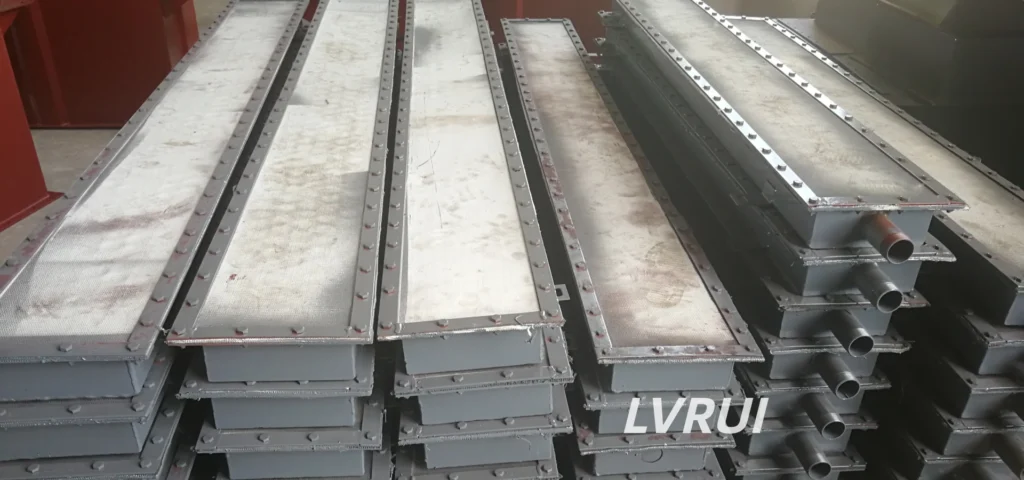
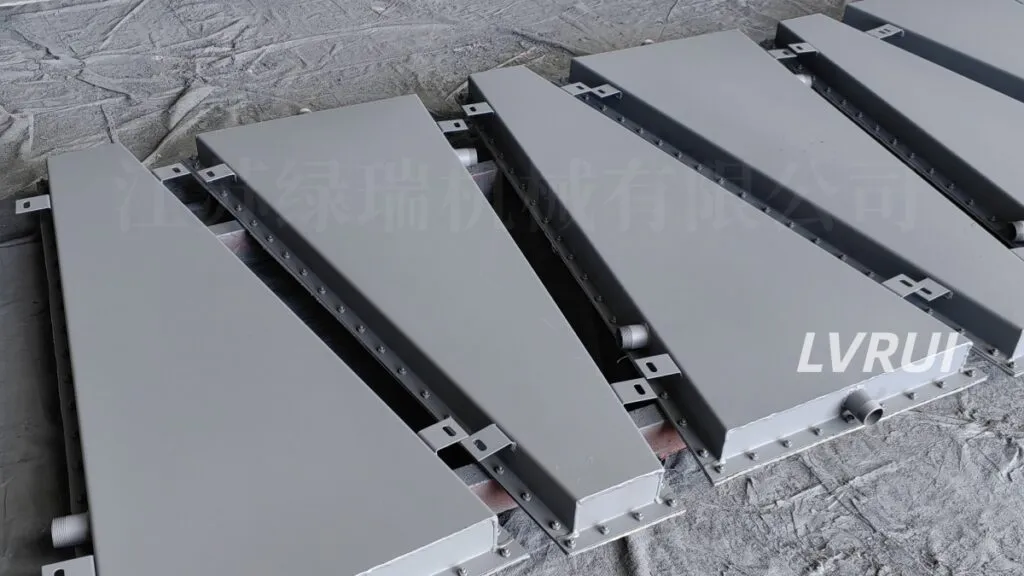
How to Improve Cement Silo Discharge Stability with Better Aeration Pad Layout
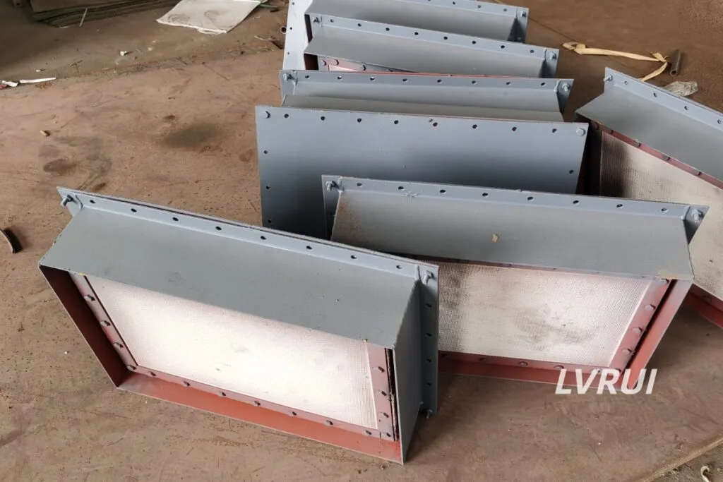
What Is Aeration Pads Placement Design?
Aeration pads placement design determines how low-pressure air is distributed inside cement silo cones. A good aeration pads placement design helps reduce bridging, stagnant zones and unstable discharge, while poor placement may cause over-fluidization, air channeling or uneven material flow.
Aeration pads are not installed randomly. Their position should match the silo cone angle, outlet size, cement flow behavior, discharge rate, air supply condition and downstream equipment layout. In many cement silo projects, the correct placement is more important than simply increasing the number of aeration pads.
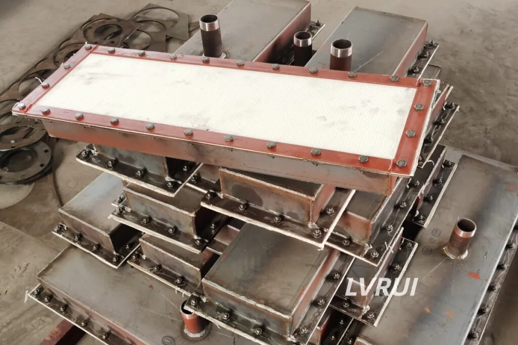
In cement plants, aeration pads are commonly used in silo cones, hopper bottoms and discharge zones where powder may compact after long storage. They can work together with flow control gates, slide gate valves, screw conveyors, air slide conveyors, bulk loaders and bag filters to support stable dry powder handling.
Why Aeration Pad Placement Matters More Than Quantity
In many cement silo projects, aeration pads placement design is more important than simply increasing the number of pads.
Many silo discharge problems are not caused by a lack of aeration pads. They are caused by poor placement, uneven airflow or a layout that does not match the material flow pattern.
Adding more pads without checking the silo geometry may create new problems. Too much air near the outlet may cause local over-fluidization, air channeling or unstable discharge. Too few pads in high-pressure cone zones may leave compacted cement untouched.
A good aeration pads placement design should help achieve:
✅ Stable cement discharge from the silo cone
✅ Reduced bridging and rat-holing
✅ Better airflow distribution inside the cone
✅ Less manual cleaning around discharge points
✅ Smoother feeding into downstream conveyors
✅ Lower risk of sudden material surges
✅ Better coordination with valves and silo outlet equipment
✅ Easier maintenance and replacement of aeration pads
The goal is not to inject the maximum amount of air. The real goal is to apply controlled air at the right locations.
How Cement Flows Inside Silo Cones
Before designing the aeration pad layout, it is important to understand how cement behaves inside a silo cone.
Cement powder can become compacted during storage because of material weight, long storage time, moisture sensitivity and silo pressure. When discharge starts, cement may not flow evenly across the whole cone. Some zones move quickly, while other zones remain stagnant.
Common cement silo discharge problems include:
✅ Bridging above the outlet
✅ Rat-holing in the center flow channel
✅ Slow discharge near cone wall areas
✅ Sudden material collapse after delayed flow
✅ Uneven feeding into conveyors or valves
✅ Dust surge during unstable discharge
✅ Material buildup around dead zones
Aeration pads are used to improve flow behavior by introducing low-pressure air into selected cone zones. The layout should support gradual and balanced fluidization instead of strong local air injection.This is why aeration pads placement design should be based on material flow behavior, not only on the silo outlet position.
For general industrial dust control and mineral material handling reference, see the NIOSH Dust Control Handbook for Industrial Minerals Mining and Processing.
Rule 1: Start from the Lower Cone Zones
The lower cone zone is usually the most critical area for cement discharge. This is where material pressure is high and where bridging or slow flow often begins.
Aeration pads should be placed near the lower cone area, but not always directly at the outlet. If pads are placed too close to the outlet only, they may fluidize a small local area while leaving upper compacted zones inactive.
A practical lower cone design should consider:
✅ Distance from the outlet
✅ Cone angle
✅ Outlet diameter
✅ Cement consolidation pressure
✅ Available installation space
✅ Downstream valve or conveyor position
✅ Maintenance access around the silo bottom
For small silos, one lower aeration zone may be enough. For larger silos, lower pads should often work together with intermediate pads to create a smoother flow path.For this reason, aeration pads placement design should start from the lower cone zone but should not be limited to the outlet area only.
Rule 2: Use Multi-Level Placement for Larger Silo Cones
For larger cement silos, aeration pads placement design usually requires multi-level placement instead of a single lower ring.
A multi-level layout places aeration pads at different elevations inside the silo cone. This helps distribute air more evenly and reduces the risk of material remaining compacted above the outlet.
Common multi-level placement patterns include:
✅ Lower ring layout near the discharge zone
✅ Intermediate ring layout in the middle cone area
✅ Staggered layout between different elevation levels
✅ Targeted layout for known stagnant zones
✅ Asymmetric layout for retrofit silos with uneven flow
Multi-level placement is especially useful when the silo has a large diameter, steep discharge demand or historical bridging problems.
Rule 3: Avoid Placing All Pads Too Close to the Outlet
It may seem logical to place aeration pads as close as possible to the outlet. But this is not always the best design.
If all pads are concentrated near the outlet, air may escape through the shortest path instead of helping the entire cone discharge. This can cause local fluidization without solving the main compaction problem.
Possible risks include:
✅ Local over-fluidization near the outlet
✅ Air channeling through one path
✅ Uneven discharge from upper cone areas
✅ Sudden material surges
✅ Poor control before valves or conveyors
✅ Low improvement in stagnant zones
A better layout usually distributes pads across the critical cone zones, not only at the bottom.
Rule 4: Match Pad Position with Cone Angle and Silo Geometry
Silo cone geometry directly affects cement flow. A steeper cone may support better gravity flow, while a shallow cone may create more stagnant zones near the wall.
Aeration pads placement design should be adjusted according to:
| Design Factor | Why It Matters |
|---|---|
| Cone angle | Affects material stress, wall friction and flow path. |
| Silo diameter | Larger silos often need multi-level or staggered placement. |
| Outlet size | Small outlets increase bridging and unstable discharge risk. |
| Cone height | Affects how material pressure is distributed inside the cone. |
| Wall condition | Rough or worn surfaces may increase material buildup. |
| Retrofit condition | Existing silos may have limited installation space. |
A standard layout cannot be copied blindly from one silo to another. Even if two silos store cement, their cone angle, outlet structure and discharge behavior may be different.
Rule 5: Balance Airflow Between Different Pad Zones
Good placement is only part of the design. Airflow balance is equally important.
If one group of aeration pads receives too much air and another group receives too little, cement flow may become unstable. In some cases, the problem is not the pad location but the air distribution system.
Airflow balance should consider:
✅ Air pressure
✅ Air volume
✅ Pipe diameter
✅ Air distribution manifold
✅ Number of pads per air line
✅ Distance from blower or air source
✅ Valve control for different pad zones
✅ Maintenance condition of aeration fabric
Aeration pads should create controlled fluidization, not aggressive air injection. Excessive air may disturb the material bed and increase dust movement.Good aeration pads placement design must combine correct pad position with balanced airflow control.
Rule 6: Coordinate Aeration Pads with Downstream Equipment
Aeration pads do not work alone. Their placement must be coordinated with downstream silo discharge equipment.
If the aeration layout creates unstable flow, downstream equipment may receive sudden material surges. This can overload conveyors, valves or loading systems.
Common downstream equipment includes:
✅ Flow control gate valves
✅ Slide gate valves
✅ Screw conveyors
✅ Air slide conveyors
✅ Rotary valves
✅ Bulk loaders
✅ Loading spouts
✅ Bag filters
✅ Powder transfer systems
For systems feeding into an air slide conveyor, a balanced and gradual fluidization profile is essential to maintain stable material flow
For controlled silo discharge, aeration pad placement should also be coordinated with flow control gate valves
For complete powder handling layouts, see our cement silo discharge system
Rule 7: Design for Maintenance Access
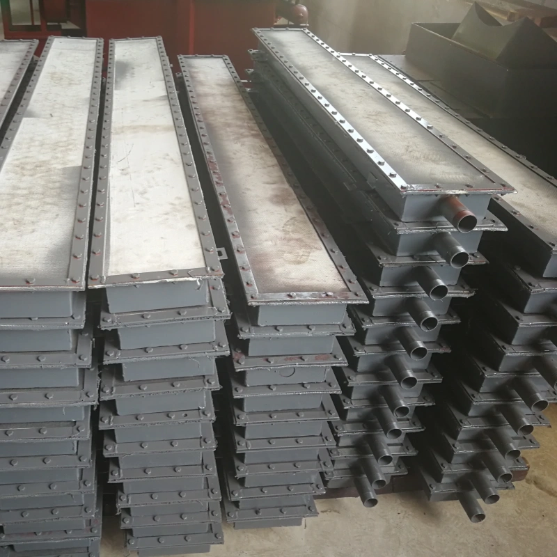
Aeration pads are wear parts. Even a good layout can fail if the pads cannot be inspected, cleaned or replaced when needed.
Maintenance access should be considered during the placement design stage. If pads are installed in locations that are difficult to reach, later maintenance becomes expensive and time-consuming.
A practical layout should allow:
✅ Pad inspection
✅ Fabric replacement
✅ Air pipe checking
✅ Valve maintenance
✅ Cleaning of blocked lines
✅ Safe access during shutdown
✅ Clear labeling of air supply zones
For retrofit projects, maintenance access can be more important than theoretical ideal placement. A realistic design that can be maintained is better than a perfect layout that cannot be serviced.
Aeration Pads Placement Design Checklist
Use the following checklist before deciding the final layout.
| Design Factor | What to Check | Why It Matters |
|---|---|---|
| Silo type | Cement silo, fly ash silo, lime silo, powder storage silo | Different materials and silos need different layouts. |
| Silo diameter | 3 m, 5 m, 8 m or custom | Larger silos may need multi-level placement. |
| Cone angle | 45°, 55°, 60° or project-specific | Affects flow path and stagnant zones. |
| Outlet size | Round or square outlet dimension | Small outlets increase bridging risk. |
| Stored material | Cement, fly ash, lime powder, raw meal, mineral powder | Different powders have different flowability. |
| Bulk density | t/m³ or kg/m³ | Affects consolidation pressure. |
| Moisture condition | Dry, slightly damp, moisture-sensitive | Higher moisture increases poor flow risk. |
| Discharge rate | t/h | Higher discharge demand needs better air distribution. |
| Pad elevation | Lower cone, middle cone, transition zone | Determines which material zones are fluidized. |
| Air supply | Blower or compressed air source | Affects airflow stability. |
| Downstream equipment | Valve, screw conveyor, air slide conveyor, bulk loader | Determines required feeding stability. |
| Maintenance access | Available or limited | Affects long-term serviceability. |
Common Aeration Pad Layout Patterns
There is no single best layout for every silo. The following patterns are commonly used depending on silo size and discharge behavior.
| Layout Pattern | Suitable Situation | Design Notes |
|---|---|---|
| Lower Ring Layout | Small silo cones or limited discharge problems | Pads are placed near the lower cone zone to assist outlet discharge. |
| Multi-Level Ring Layout | Large silo cones or higher discharge rates | Pads are arranged at different elevations for better air distribution. |
| Staggered Layout | Uneven flow or larger cone surfaces | Pads are staggered between levels to reduce inactive zones. |
| Targeted Zone Layout | Retrofit silos with known blockage zones | Pads are installed in specific problem areas instead of symmetrical rings only. |
| Asymmetric Layout | Silos with non-uniform discharge behavior | Useful when site history shows one side has more flow resistance. |
The best layout should be based on silo geometry, material behavior and discharge requirements, not only on the number of pads.
Common Mistakes in Aeration Pad Placement
Poor aeration pads placement design can make silo discharge worse, even when the silo has enough aeration pads installed.
✅ Installing too many pads without checking material flow behavior
✅ Placing all pads too close to the discharge outlet
✅ Ignoring cone angle and silo geometry
✅ Using the same layout for every silo size
✅ Applying a symmetrical layout to an asymmetric flow problem
✅ Using excessive air pressure instead of improving pad position
✅ Ignoring moisture-sensitive cement powder
✅ Not balancing air between different pad zones
✅ Failing to coordinate aeration with valves and conveyors
✅ Installing pads where maintenance is difficult
The purpose of aeration pads is not to inject as much air as possible. The real purpose is to create stable and controlled fluidization in the zones where cement is most likely to consolidate or stop flowing.
Troubleshooting Poor Cement Discharge After Installing Aeration Pads
If cement discharge is still unstable, the first step is to review the aeration pads placement design, air pressure and downstream discharge equipment together.
Common causes include:
✅ Pads installed in the wrong cone zone
✅ Air pressure too high or too low
✅ Air distribution not balanced between different pad levels
✅ Cement moisture higher than expected
✅ Silo outlet too small for the required discharge rate
✅ Flow control gate opening not matched with aeration air supply
✅ Downstream conveyor cannot receive material steadily
✅ Aeration fabric clogged by dust, moisture or long-term operation
✅ Poor sealing around the discharge zone
✅ Existing silo geometry not suitable for the target discharge rate
In many retrofit projects, improving pad position and airflow balance is more effective than simply adding more pads.
Information Required for Aeration Pad Placement Design
To design a suitable aeration pad layout, please provide the following project information.
| Required Information | Example |
|---|---|
| Silo type | Cement silo, fly ash silo, lime silo, powder storage silo |
| Silo diameter | 3 m, 5 m, 8 m or custom |
| Cone angle | 45°, 55°, 60° or project-specific |
| Outlet size | Diameter or square outlet dimension |
| Stored material | Cement, fly ash, lime powder, raw meal, mineral powder |
| Bulk density | t/m³ or kg/m³ |
| Moisture condition | Dry, slightly damp, moisture-sensitive |
| Required discharge rate | t/h |
| Existing discharge problem | Bridging, rat-holing, slow discharge, unstable flow |
| Downstream equipment | Flow control gate, screw conveyor, air slide conveyor, bulk loader |
| Existing aeration layout | Photos or drawings if available |
| Air supply condition | Air pressure, air volume, blower or compressed air source |
| Project type | New silo, retrofit, maintenance replacement |
| Destination country | For packing and shipping reference |
This information helps engineers avoid a blind layout and design aeration pad placement according to real silo geometry and material behavior.
Aeration Pads and Complete Silo Discharge Systems
In cement plants, aeration pads are often one part of a complete silo discharge system. A good layout should match the downstream equipment.
A typical system may include:
✅ Aeration pads inside the silo cone
✅ Flow control gate for material discharge regulation
✅ Slide gate valve for shut-off or maintenance isolation
✅ Screw conveyor for short-distance controlled feeding
✅ Air slide conveyor for dry powder conveying
✅ Bag filter for dust collection
✅ Bulk loader or loading spout for final loading
For a complete dry powder handling solution, see our powder transfer system
Conclusion
.Aeration pads placement design is a key factor in cement silo discharge stability, especially for cement silos with bridging, rat-holing, slow discharge or unstable material flow. A good layout should not be based only on pad quantity. It should consider silo cone geometry, outlet size, material behavior, airflow balance, discharge rate and downstream equipment.
For small silos, lower cone placement may be enough. For larger silos, a multi-level or staggered layout is often more practical. For retrofit silos, existing flow problems and maintenance access should be checked before adding new pads.
The best aeration pad layout is the one that creates stable, controlled and maintainable powder flow inside the silo cone.
FAQ About Aeration Pads Placement Design
What is aeration pads placement design?
Aeration pads placement design refers to how aeration pads are arranged inside a cement silo cone to distribute low-pressure air and improve powder discharge. Good placement helps reduce bridging, stagnant zones and unstable flow.
Where should aeration pads be placed in a cement silo cone?
Aeration pads are usually placed in lower cone zones, intermediate cone areas and transition zones near the silo outlet. The exact position depends on silo geometry, cone angle, material flow behavior and discharge requirement.
Should aeration pads be installed close to the outlet?
Not always. Installing too many pads too close to the outlet may cause uncontrolled flow or local over-fluidization. Pads should be placed where cement consolidation and stagnant zones are most likely to occur.
How many aeration pads are needed in a cement silo?
The number depends on silo diameter, cone angle, outlet size, discharge rate, material bulk density and flow behavior. A large silo may need multi-level placement, while a small silo may only require fewer pads in critical zones.
What is the best layout pattern for aeration pads?
Common patterns include lower ring layout, staggered multi-level layout and targeted zone layout. The best pattern depends on silo size, cone shape, cement properties and whether the project is new installation or retrofit.
Can too many aeration pads cause problems?
Yes. Too many aeration pads or excessive air injection may cause over-fluidization, unstable discharge, air channeling or uneven material flow. Proper placement and air control are more important than maximum pad quantity.
Why does cement still discharge poorly after aeration pads are installed?
Poor discharge may be caused by wrong pad position, clogged fabric, insufficient air supply, excessive moisture, poor silo outlet design, incorrect valve opening or downstream conveyor limitation.
What equipment should be considered together with aeration pads?
Aeration pads should be coordinated with flow control gates, slide gate valves, screw conveyors, air slide conveyors, bulk loaders, bag filters and the complete cement silo discharge system.
What information is needed before designing aeration pad placement?
You should provide silo diameter, cone angle, outlet size, stored material, bulk density, moisture condition, discharge rate, downstream equipment and existing discharge problems. Photos or drawings are very helpful.
Are aeration pads suitable for wet cement?
Aeration pads are mainly suitable for dry and flowable powder materials. Wet or sticky cement may not fluidize properly and can still cause blockage or poor discharge. Material moisture should be checked before design.
Indonesian Short Version
Aeration pads placement design sangat penting untuk menjaga aliran material yang stabil di cone silo semen. Penempatan aeration pads yang baik membantu mengurangi bridging, stagnant zone dan aliran material yang tidak stabil.
Dalam desain silo semen, posisi aeration pads harus mempertimbangkan diameter silo, sudut cone, ukuran outlet, bulk density, kondisi moisture, discharge rate dan equipment downstream seperti flow control gate, screw conveyor atau air slide conveyor. Untuk silo besar, layout multi-level atau staggered sering lebih efektif dibanding hanya memasang pads dekat outlet.
Terlalu banyak aeration pads atau tekanan udara berlebihan dapat menyebabkan over-fluidization dan aliran tidak stabil. Karena itu, desain yang baik harus fokus pada distribusi udara yang seimbang, bukan hanya jumlah pads.
Untuk penawaran, kirim diameter silo, cone angle, outlet size, material, discharge rate, foto atau drawing layout proyek.
Need professional guidance on aeration pad placement design for your cement silo project?
Contact LVRUI today for expert technical support and fast quotation.
📧 Email: info@lvrui-conveyor.com
🌐 Website: https://www.lvrui-conveyor.com