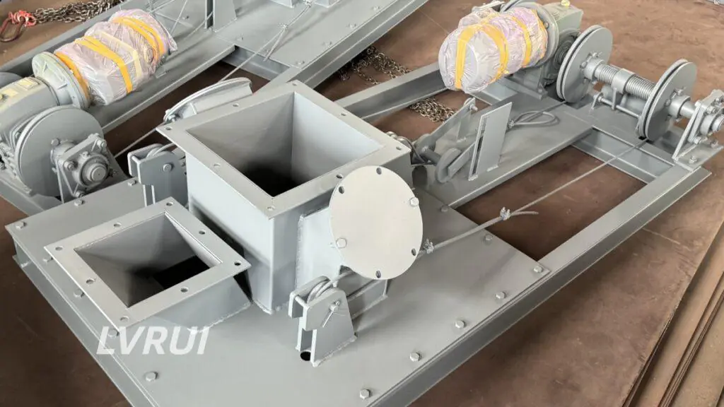
How Material Feeding, Loading Equipment, Dust Control and Automation Work Together
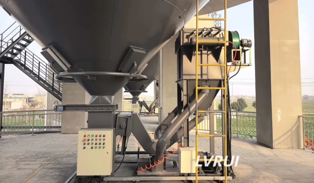
Bulk Loading System Engineering focuses on how material feeding, flow control, conveying equipment, loading spouts, dust extraction, level detection and control interlocks work together as one system. Reliable performance depends on matching these interfaces rather than evaluating each component independently.
What Is a Bulk Loading System?
A bulk loading system is a coordinated arrangement of equipment used to transfer dry bulk material from storage or conveying equipment into a truck, tanker or other receiving point.
Depending on the project, the system may include:
- Upstream conveying equipment
- Flow control or isolation devices
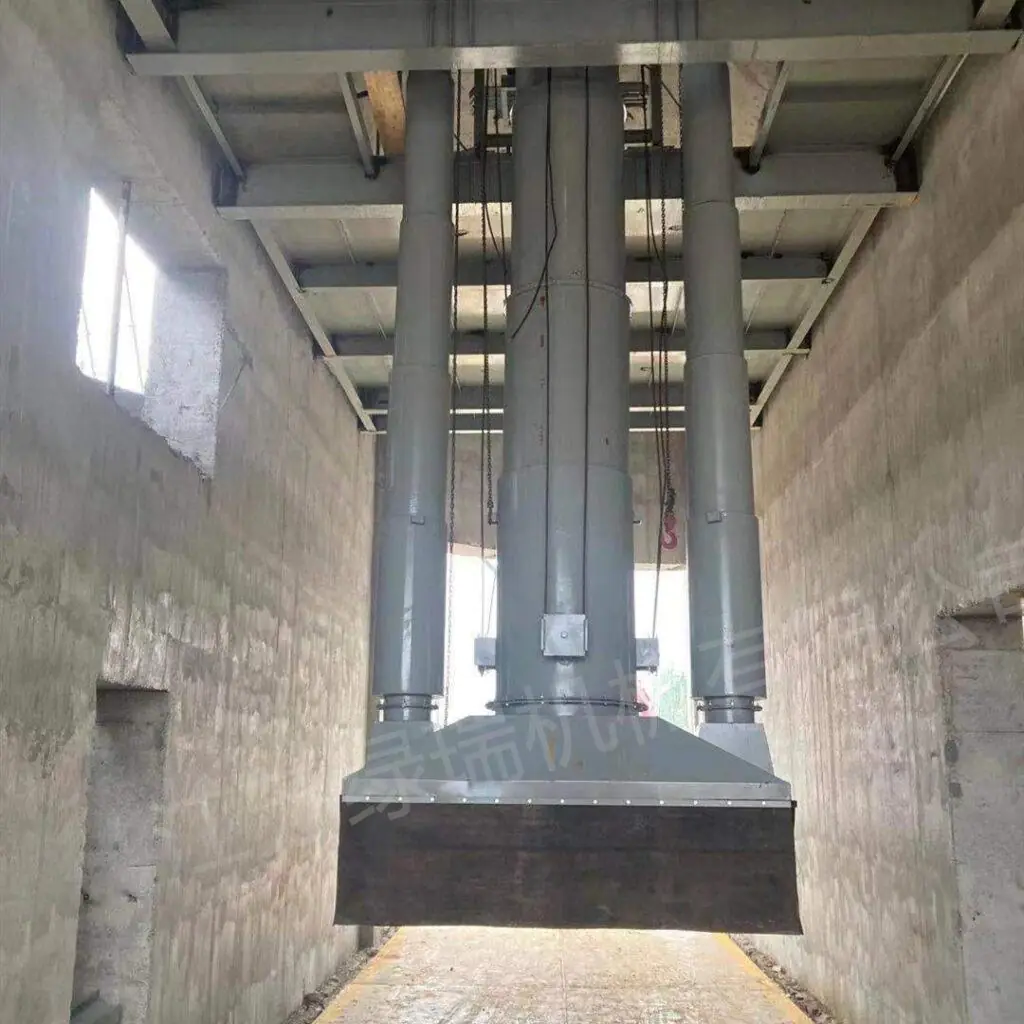
- A loading spout or loading chute
- Dust extraction
- Level detection
- Lifting equipment
- Electrical controls and interlocks
The loading spout is one component of the system, not the complete loading system by itself.
System performance therefore depends on how these components are matched and controlled rather than on the loading spout alone.
Typical Bulk Loading System Architecture
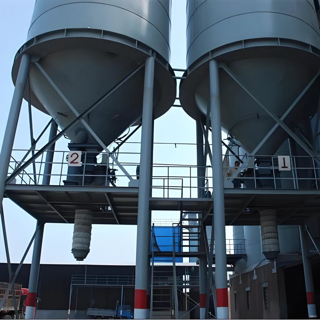
A typical powder loading line can be represented as:
Silo or Hopper → Flow Control → Conveying Equipment → Loading Spout → Receiving Vehicle
Supporting equipment may include:
Dust Extraction + Level Detection + Control Interlocks
Each section has a separate function.
Storage and discharge equipment
Makes material available to the downstream process.
Flow control equipment
Regulates or isolates material entering the conveying and loading section.
Conveying equipment
Transfers material from the silo discharge point to the loading station where required.
Loading spout or chute
Guides material into the receiving vehicle while helping contain displaced air and dust.
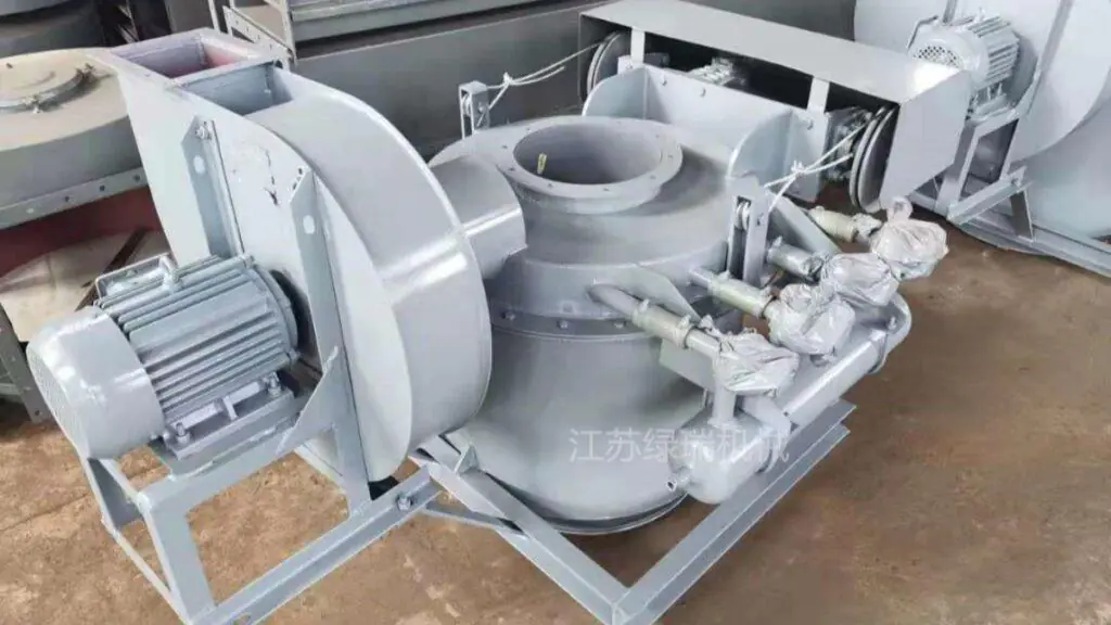
Dust extraction
Removes dust-laden air generated around the loading interface.
Level detection and controls
Coordinate material feeding, lifting and stopping functions.
A reliable bulk loading system therefore depends on the complete material and control path rather than one individual component.
For available equipment configurations, see our Bulk Loader System product page.
Main Engineering Interfaces in a Bulk Loading System
In bulk loading system engineering, each interface should be evaluated as part of the complete material and control path.
Material Feed Interface
The upstream conveyor or silo outlet must be able to supply material at a rate compatible with the loading station.
Possible feeding equipment includes:
- Air slide conveyors
- Screw conveyors
- Gravity discharge
- Other suitable bulk conveying equipment
Flow Control Interface
A flow control gate or other suitable discharge device may be used to regulate material entering the loading section.
The objective is to avoid feeding the loading equipment faster than the downstream system can receive material.
Loading Interface
The loading spout or chute provides the final connection between the material stream and the truck, tanker or receiving point.
Its dimensions, extension range and sealing arrangement should match the receiving vehicle and material.
Dust Extraction Interface
Dust extraction must be coordinated with the loading head, duct arrangement and displaced-air volume.
Control Interface
Level switches, limit switches and upstream equipment signals can be combined so the system starts, stops and retracts in the required sequence.
Different Loading Targets Require Different System Arrangements
The same bulk loading concept can be adapted to different receiving conditions.
Enclosed Tankers
Fine powders such as cement and fly ash are commonly loaded through a relatively enclosed interface where sealing and displaced-air management are important.
Open Trucks
Open loading requires greater attention to drop height, dust containment and the position of the loading head as the material level rises.
Railcars and Other Receiving Points
The same engineering principles apply, but equipment travel, support structure, loading position and dust collection requirements may differ.
The receiving target should therefore be defined before the loading equipment and control sequence are finalized.
Why System Capacity Is Not Defined by the Loading Spout Alone
The nominal capacity of a loading spout does not automatically equal the actual loading capacity of the complete system.
The final loading rate may be limited by:
- Silo discharge capacity
- Flow control opening
- Upstream conveyor capacity
- Material flowability
- Loading spout cross-section
- Receiving vehicle condition
- Dust extraction capacity
- Control sequence
For example, installing a loading spout rated for a higher throughput will not increase system output if the upstream air slide or flow control device remains the limiting component.
For this reason, capacity should be checked across the complete material path.
Coordinating Flow Control and Upstream Conveying
Bulk loading becomes unstable when the loading section and upstream material supply are not properly matched.
A typical sequence may be:
Silo Discharge → Flow Control Gate → Air Slide or Screw Conveyor → Loading Spout
The flow control device regulates material entering the downstream path.
The conveyor transfers material toward the loading station.
The loading spout manages the final loading interface.
These functions should not be treated as interchangeable.
Increasing gate opening cannot compensate for insufficient conveyor capacity, and increasing conveyor capacity does not solve a restriction at the loading point.
The complete system should therefore be reviewed from source to receiving vehicle.
Dust Control Must Be Designed as Part of the Loading Interface
Dust generation during bulk loading is strongly influenced by material drop, displaced air and how well the loading point is enclosed.
A dust-control arrangement may include:
- An enclosed or partially enclosed loading head
- Dust extraction connection
- Flexible sealing
- External or integrated dust collector
- Appropriate ductwork
The dust collector should not be evaluated independently from the loading point.
Poor sealing, excessive air leakage or unsuitable duct resistance can reduce dust capture even when the filter itself is operating normally. General engineering principles for controlling airborne dust at material transfer points are also covered in the UK Health and Safety Executive’s local exhaust ventilation guidance.
For truck- and tanker-specific dust-control arrangements, see the dedicated Dust-Free Bulk Truck Loading System page.
Level Detection and Control Interlocks
Automation is most useful when equipment responses are coordinated.
Depending on the system configuration, the control sequence may include:
- Position the loading spout
- Confirm the loading head is in the permitted position
- Start dust extraction
- Enable material feeding
- Monitor the receiving level
- Stop upstream material flow at the required level
- Allow residual material to clear
- Retract the loading spout
Level switches, limit switches and equipment status signals can be used to coordinate these actions.
The exact sequence should match the mechanical arrangement and operating requirements of the project.
Common Bulk Loading System Integration Problems
Many loading problems are caused by mismatched equipment rather than failure of the loading spout itself.
Typical examples include:
Upstream Capacity Is Too High
Material reaches the loading point faster than it can be discharged or controlled.
Dust Extraction Is Not Matched to the Loading Point
Dust escapes because the extraction path, sealing or airflow is inadequate.
Loading Range Does Not Match the Vehicle
The spout cannot maintain the intended position through the required loading cycle.
Control Signals Are Not Interlocked
Material flow continues when the loading head is not in the correct position or when the receiving point is already full.
Material Properties Were Not Considered
Sticky, abrasive or poorly flowing material may behave differently from the design assumption.
System troubleshooting should therefore follow the complete process path rather than focusing on one component first.
Installation Interfaces to Check Before Commissioning
At system level, verify:
- Mechanical alignment between connected equipment
- Structural support
- Loading-spout travel clearance
- Dust duct connection
- Electrical and control interfaces
- Vehicle positioning
- Upstream and downstream interlocks
For detailed loading-spout mounting, vertical alignment and commissioning procedures, see our Bulk Loading Spout Installation Guide.
FAQs About Bulk Loading System Engineering
What equipment is included in a bulk loading system?
A system may include upstream conveying equipment, flow control devices, a loading spout or chute, dust extraction, level detection, lifting equipment and electrical controls. The exact configuration depends on the project.
Is a loading spout the same as a bulk loading system?
No. A loading spout is the final loading component. A bulk loading system may include the complete material, dust-control and automation path around it.
What determines the actual loading capacity?
Actual capacity depends on the complete material path, including silo discharge, flow control, conveyor capacity, material properties, loading equipment and receiving conditions.
Why is dust generated during bulk loading?
Dust may be generated by material free fall, impact and displaced air. Effective control depends on the loading interface, sealing, extraction airflow and dust collector arrangement.
Can an existing silo be connected to a new bulk loading system?
In many projects, yes. The existing outlet, conveying equipment, support structure, available space, electrical interfaces and required loading capacity should be reviewed first.
What information is needed to review a bulk loading system?
Useful information includes the material, bulk density, required capacity, silo outlet, existing conveyor, truck or tanker dimensions, loading height, dust-control requirement and available layout drawings.
Conclusion
Effective bulk loading system engineering requires the loading process to be evaluated as an integrated material-handling system rather than as a loading spout alone.
Reliable performance depends on coordination between:
Material Supply → Flow Control → Conveying → Loading Interface → Dust Extraction → Level Detection and Controls
When these interfaces are matched correctly, the loading station can operate more consistently without relying on any single component to solve every system limitation.
Need Help Reviewing a Bulk Loading System Layout?
Send us the material, bulk density, required loading capacity, silo outlet dimensions, existing conveying equipment, truck or tanker dimensions, loading height, dust-control requirements, and available drawings or site photos.
LVRUI can review the equipment interfaces and recommend a suitable bulk loading system configuration for equipment supply.
WhatsApp: +86 18261998937
WeChat: +86 18261998937
Email: info@lvrui-conveyor.com