How Does a Double Dump Valve Work?

Double Dump Valve Working Principle, Operating Cycle and Common Problems


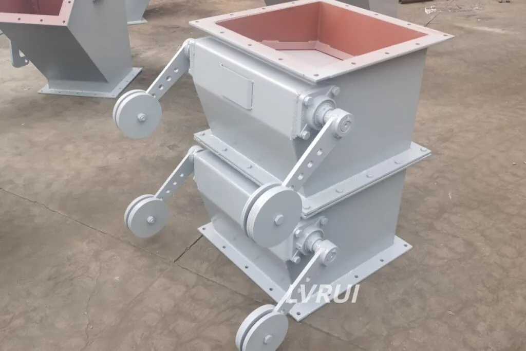
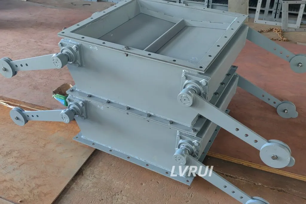
Double dump valve working principle showing the upper and lower flap operating sequence

What Happens Inside a Double Dump Valve?

A double dump valve, also called a double flap valve, contains an upper flap, an intermediate chamber and a lower flap arranged vertically.

Its operating principle is based on sequential movement. Material first passes through the upper flap into the intermediate chamber. The upper flap then closes before the lower flap opens and releases the material.

The two flaps should not remain open at the same time during normal operation. At least one closed flap separates the upstream and downstream equipment, helping restrict a direct airflow path through the valve.

This makes the valve different from a simple open chute or single gate. Its main function is not precise feeding, but controlled cyclic discharge while maintaining partial pressure isolation.

For available structures, drive options and customized dimensions, refer to the LVRUI double flap valve product page.


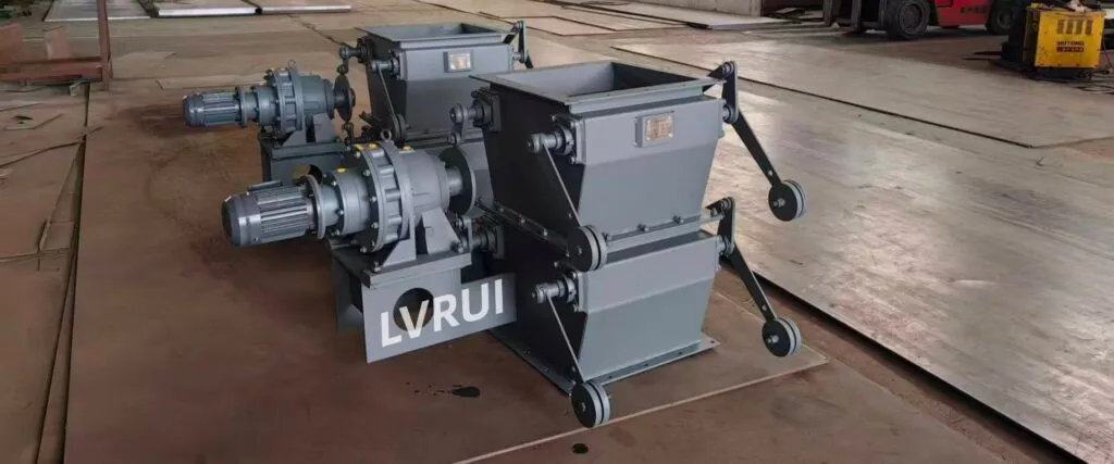
Double flap valve for bulk material discharge in cement plant

Double Dump Valve Working Principle: The Four-Stage Operating Cycle

The working sequence can be divided into four stages.

Stage 1: The Upper Flap Opens

At the beginning of the cycle, the lower flap remains closed.

The upper flap opens and allows material from the hopper, silo or dust collector outlet to fall into the intermediate chamber.

The chamber must be large enough to receive the material entering during this stage. If it fills too quickly, material may remain above the upper flap and interfere with closing.

Stage 2: The Upper Flap Closes

After the chamber has received the required amount of material, the upper flap returns to its closed position.

This is a critical step. The upper flap should close completely before the lower flap begins opening.

If material becomes trapped between the flap and its seating surface, the valve may develop excessive air leakage or fail to maintain the required pressure separation.

Stage 3: The Lower Flap Opens

Once the upper flap is confirmed closed, the lower flap opens.

The material stored in the intermediate chamber falls into the downstream chute, conveyor or receiving equipment under gravity.

The chamber must have sufficient time to empty. Opening and closing the lower flap too quickly can leave residual material inside the chamber.

Stage 4: The Lower Flap Closes

After discharge, the lower flap closes and the valve returns to its initial condition.

The next cycle begins only after the lower flap has reached its closed position.

This repeated sequence produces intermittent discharge at each flap, although the overall material flow can appear regular when the cycle frequency is stable.


Why Must One Flap Remain Closed?

The airlock function depends on preventing a direct open passage through both stages of the valve.

If the upper and lower flaps open together, air can move directly between the upstream and downstream equipment. Depending on the process conditions, this may cause:

  • Loss of negative pressure
  • Reverse airflow through the discharge point
  • Increased dust movement
  • Unstable hopper discharge
  • Reduced dust collector performance
  • Uncontrolled material flow
  • Pressure fluctuations in connected equipment

The valve therefore needs a reliable mechanical or electrical interlock.

The control system should not rely only on a timer when flap position is critical. Limit switches or position sensors can confirm that one flap is fully closed before the other is allowed to open.

For broader reference on sequential dust collector discharge arrangements, see the OSHA guidance on dry type dust collector discharge valves.


How Is the Flap Sequence Controlled?

The sequencing method depends on the valve mechanism.

Mechanical Cam or Linkage Control

Some motorized valves use cams, shafts or linkages to coordinate the two flaps.

The geometry of the mechanism creates a fixed operating sequence. When correctly adjusted, one flap completes its closing movement before the other starts opening.

Wear, loose linkages or incorrect cam positioning can change this sequence over time.

Pneumatic Control

Pneumatic systems normally use separate cylinders, solenoid valves and control signals for the upper and lower flaps.

Opening time, closing time and delay intervals can be adjusted through the PLC or local controller.

Position switches are useful because cylinder movement can vary when air pressure changes or material obstructs the flap.

Counterweight Operation

Counterweight designs rely on material weight and mechanical balance.

As material accumulates, its weight overcomes the counterweight and opens the flap. The flap returns after the material is discharged.

This design is mechanically simple, but the timing depends more heavily on material flow, counterweight adjustment and flap condition.

Regardless of the mechanism, the essential rule remains the same:

One flap must close before the other flap opens.


How Does Cycle Timing Affect Discharge?

Cycle timing has a direct effect on valve performance.

If the Cycle Is Too Fast

The intermediate chamber may not fill properly before the upper flap closes.

The lower flap may also close before all material has left the chamber. This can produce:

  • Low discharge capacity
  • Irregular flow
  • Material trapped beneath the flap
  • Increased impact and wear
  • More frequent actuator movement

Running the valve faster does not always increase its useful capacity.

If the Cycle Is Too Slow

Material may accumulate above the upper flap while it remains closed.

In some systems, this can increase the risk of bridging, compacted material or unstable upstream discharge.

A slow cycle can also create noticeable batch fluctuations in the downstream process.

If Upstream Feeding Is Unstable

Even correctly timed flaps cannot produce uniform discharge when the incoming material flow changes significantly.

The cycle should be coordinated with:

  • The upstream material accumulation rate
  • Intermediate chamber volume
  • Material flowability
  • Downstream receiving capacity
  • Required pressure isolation

The correct cycle is therefore an operating balance rather than a fixed universal setting.


Is Double Dump Valve Discharge Continuous?

A double dump valve provides cyclic discharge.

The upper and lower flaps operate intermittently, and each opening releases a separate quantity of material. However, repeated cycles can produce a relatively regular average flow.

It should not be described as a precision continuous feeder because the amount discharged during each cycle can change with:

  • Chamber filling level
  • Material bulk density
  • Flowability
  • Cycle duration
  • Residual material
  • Upstream feeding stability

Where accurate dosing or highly uniform continuous feeding is required, separate metering equipment may be necessary.

For a detailed comparison of the operating principles, refer to the guide on double flap valve vs rotary valve selection.


Factors Affecting Airlock Performance

The presence of two flaps alone does not guarantee effective airlock operation.

Several factors influence actual performance.

Flap Closing Condition

The flap must return to the correct closed position after each movement.

Wear, deformation, misalignment or material trapped on the seating surface can prevent complete closing.

Pressure Difference

A higher pressure difference can increase the force acting on the flap and may also increase leakage through available clearances.

The actuator and flap structure must be capable of operating under the actual process pressure.

Intermediate Chamber Volume

The chamber must hold the quantity of material entering during the upper-flap stage.

An undersized chamber can overfill, while an oversized chamber may require a longer discharge period.

Material Behaviour

Fine powder, abrasive particles and irregular lumps interact differently with the flap and seating surface.

Material that compacts, sticks or forms deposits can interfere with flap movement even when the drive mechanism is operating normally.

Shaft and Bearing Condition

Resistance in the shaft, bearing or linkage can slow flap movement and prevent reliable closing.

Regular inspection is especially important where dust can enter external moving parts.


Common Double Dump Valve Problems and Checks

Both Flaps Open at the Same Time

This is a serious sequencing problem because it creates a direct passage through the valve.

Check:

  • PLC interlock logic
  • Cam or linkage position
  • Limit-switch signals
  • Solenoid valve timing
  • Cylinder movement
  • Loose drive components

Operation should be stopped until the sequence is corrected.

The Upper Flap Does Not Close Completely

Common causes include:

  • Material trapped beneath the flap
  • Worn seating surfaces
  • Insufficient actuator force
  • Shaft misalignment
  • Compacted powder
  • Incorrect counterweight adjustment

The chamber filling time may also be too long, allowing excessive material to accumulate.

The Lower Flap Does Not Empty the Chamber

Check whether:

  • The opening time is too short
  • Material is sticky or compacted
  • The discharge chute is restricted
  • The flap opening angle is insufficient
  • Residual material is building up inside the chamber
  • Downstream equipment is blocking the outlet

Increasing the cycle frequency will not solve a restricted discharge passage.

Excessive Air Leakage Through the Valve

Air leakage can result from:

  • Both flaps opening together
  • Worn or damaged flap edges
  • Material trapped on the sealing surface
  • Incorrect closing position
  • Excessive process pressure
  • Flap or shaft deformation
  • Loose mechanical linkages

The first inspection should determine whether the problem is caused by sequencing or incomplete mechanical closing.

Irregular Discharge Rate

An uneven discharge rate may result from:

  • Unstable upstream feeding
  • Incorrect cycle timing
  • Incomplete chamber filling
  • Incomplete chamber emptying
  • Changes in material bulk density
  • Material bridging above the inlet
  • Inconsistent pneumatic pressure

Observe several complete cycles rather than checking only one flap movement.

Frequent Mechanical Wear

Accelerated wear may indicate:

  • Excessive cycling speed
  • Abrasive material impact
  • Flap slamming
  • Incorrect counterweight adjustment
  • Misaligned shafts
  • Material trapped during closing
  • Insufficient wear protection

The source of the wear should be corrected instead of only replacing the worn component.

Routine Operating Checks

Regular inspection should focus on the parts that directly affect flap sequencing and closing.

Check:

  • Upper and lower flap movement
  • Closing positions
  • Limit-switch response
  • Cam and linkage condition
  • Cylinder or motor operation
  • Counterweight adjustment
  • Shaft and bearing movement
  • Material accumulation
  • Flap seating surfaces
  • Abnormal noise or impact

The equipment should be isolated before internal inspection or material removal.


Double flap valve working principle diagram

Frequently Asked Questions

Why must one flap remain closed during operation?

A closed flap prevents a direct airflow path between the upstream and downstream equipment. This helps maintain pressure separation while the other flap receives or discharges material.

Can both flaps open at the same time?

They should not remain open together during normal operation. Simultaneous opening reduces the airlock effect and may cause pressure loss, reverse airflow or increased dust movement.

Is the discharge continuous or intermittent?

Each flap discharges intermittently. Repeated alternating cycles can provide a regular average flow, but the valve is not a precision continuous feeder.

How is the flap sequence controlled?

Common causes include incorrect flap timing, incomplete closing, worn seating surfaces, trapped material, misalignment and excessive pressure difference.

What causes excessive air leakage?

Common causes include incorrect flap timing, incomplete closing, worn seating surfaces, trapped material, misalignment and excessive pressure difference.

What happens if material becomes trapped beneath a flap?

Common causes include incorrect flap timing, incomplete closing, worn seating surfaces, trapped material, misalignment and excessive pressure difference.


Learn More About LVRUI Double Flap Valves

To explore available drive options, valve structures, and customized configurations, visit the LVRUI double flap valve product page.

LVRUI provides technical drawings, operating instructions, and remote technical guidance for overseas projects.

Email: info@lvrui-conveyor.com
WhatsApp: +86 18261998937
WeChat: +86 18261998937


Indonesian Short Version

Double dump valve menggunakan dua flap yang membuka dan menutup secara bergantian. Material pertama masuk ke ruang tengah melalui flap atas. Flap atas kemudian menutup sebelum flap bawah membuka dan membuang material.

Minimal satu flap harus tetap tertutup selama siklus operasi. Jika kedua flap terbuka bersamaan, udara dapat mengalir langsung melalui valve dan mengurangi fungsi airlock.

Waktu siklus harus sesuai dengan volume ruang tengah, aliran material, tekanan sistem, dan kapasitas pembuangan. Siklus yang terlalu cepat dapat menyebabkan ruang tidak terisi atau kosong dengan sempurna. Masalah umum meliputi kebocoran udara, flap tidak menutup, material terjepit, urutan gerakan salah, dan pembuangan tidak stabil.

Pemeriksaan harus mencakup posisi flap, limit switch, linkage, actuator, shaft, bearing, dan penumpukan material.