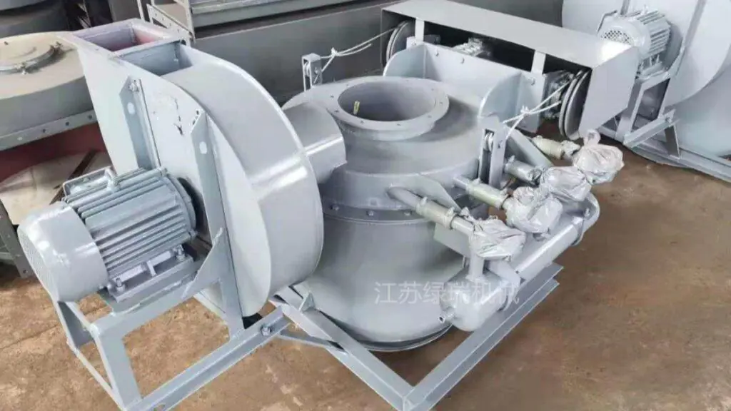
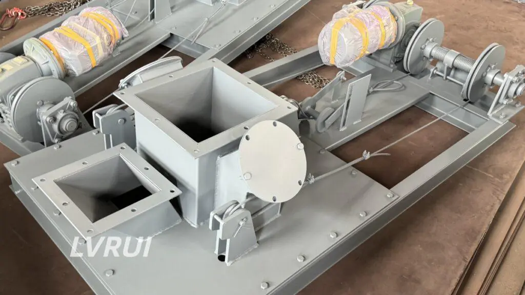
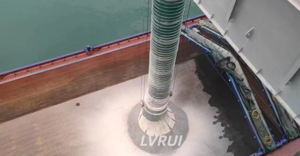
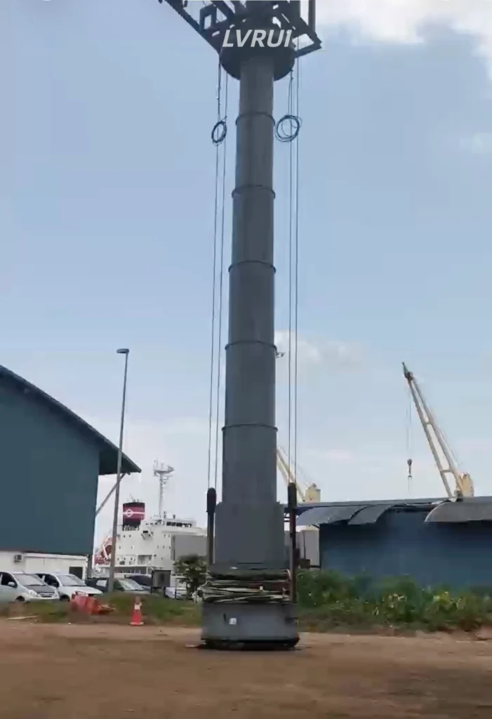
A ship loading spout site survey helps verify the mounting interface, telescopic travel, ship-hold clearance, dust extraction connection, lifting arrangement, and control interfaces before replacing a spout on an existing port loading system. This checklist covers eight essential checks to identify compatibility issues before retrofit.
For equipment configurations and supply options, see our Ship Loading Spout page.
1. Check the Inlet Flange and Mounting Interface
The inlet flange determines whether the replacement spout can connect to the existing equipment.
Record the following dimensions:
- Flange width and height, or outside diameter
- Flange thickness and bolt-hole diameter
- Bolt-hole spacing and mounting orientation
- Connection centerline and support arrangement
Compare these measurements with the original drawings. If drawings are unavailable, provide clear photographs and measured dimensions.
Do not assume that a replacement spout will fit simply because its nominal size matches the existing equipment.
For general installation considerations, see our Bulk Loading Spout Installation Guide.
2. Confirm the Mounting Elevation and Operating Range
The installation height determines the vertical operating range required for the replacement spout.
Measure the distance from a defined mounting reference point to the required discharge positions. Where relevant, account for changes in the relative elevation between the loading equipment and the vessel caused by tide or vessel draft.
Confirm:
- Existing mounting elevation
- Highest and lowest required discharge positions
- Available vertical clearance
- Any changes in operating height during loading
These measurements establish the operating envelope that the replacement equipment must accommodate. A ship loading spout site survey should account for the full operating height range, including changes in vessel elevation during loading.
3. Determine the Required Telescopic Travel
Overall length and telescopic travel are different specifications and should not be used interchangeably.
- Overall length: The total equipment length in the specified configuration.
- Telescopic travel: The distance through which the discharge end extends or retracts.
- Retracted height: The space occupied when the spout is raised.
Check whether the required travel is sufficient to reach the loading position while allowing the spout to retract without interfering with overhead beams, platforms or other structures.
The replacement configuration should be based on actual operating requirements rather than the old spout’s overall length alone.
For additional background, see our Telescopic Loading Chute Guide.
4. Check Ship-Hold Openings and Loading Coverage
The vessel layout determines whether the existing equipment can reach the intended loading positions.
Obtain a general arrangement drawing or measurements showing:
- Relevant ship-hold and hatch-opening dimensions
- Hatch coamings and nearby obstructions
- Distance between the spout centerline and target loading positions
- Available horizontal movement of the existing equipment
A vertical telescopic spout does not automatically provide horizontal positioning. If multiple loading positions must be reached, confirm that the existing conveyor or supporting structure provides the necessary movement.
5. Confirm Material Characteristics and Required Capacity
The replacement spout must suit the material and required loading conditions.
| Parameter | Information to provide |
|---|---|
| Material | Cement, clinker, mineral powder or other bulk material |
| Bulk density | Actual or estimated value, if available |
| Particle characteristics | Size and abrasiveness |
| Operating conditions | Moisture and temperature, where relevant |
| Required capacity | Target loading rate in t/h |
| Feeding arrangement | Existing conveyor or upstream feeder |
Material properties affect equipment configuration and wear considerations. The existing feeding system must also be capable of supplying the required loading rate.
Replacing the spout alone does not guarantee an increase in overall system throughput.
6. Verify the Dust Extraction Connection
For cement, clinker and other dusty bulk materials, check the existing dust extraction arrangement before selecting a replacement spout.
Record:
- Dust duct diameter and connection flange dimensions
- Connection orientation and available installation space
- Existing dust collector and fan configuration
- Available airflow or design data, if known
- Duct routing and potential interference points
The compatibility of the existing dust collection system must be assessed rather than assumed. Dust control depends on the spout configuration, loading conditions and extraction performance.
If the existing installation has a dust leakage problem, refer to our Loading Spout Dust Leakage Guide.
7. Inspect the Lifting Mechanism and Supporting Structure
Check the lifting mechanism type, available travel, cable or chain arrangement, mounting points and structural clearance. Also confirm that there is sufficient access for maintenance.
The existing winch or suspension arrangement should not be reused without confirming its suitability for the replacement equipment’s weight, travel and operating loads.
Any required structural modifications should be reviewed by the responsible engineer.
8. Confirm Electrical and Control Interfaces
Electrical compatibility must be established before manufacturing if the replacement spout uses an electric lifting mechanism or automated controls.
Confirm the following:
- Power supply voltage and frequency
- Motor and lifting control arrangement
- Upper and lower limit switches
- Local and remote operating modes
- PLC/DCS interface requirements, where applicable
- Existing interlocks and position feedback
Provide the relevant wiring diagrams or control cabinet information when available. Also clarify responsibility for installation, electrical connections and integration with the existing system.
For U.S. marine terminals, review applicable requirements, including OSHA 29 CFR 1917.49, where relevant to the installation and operation.
Ship Loading Spout Site Survey Checklist: Information for a Quotation
Prepare the following information before contacting a supplier:
- Recent photographs of the existing spout, mounting interface and surrounding structure
- Existing drawings or measured flange dimensions
- Mounting elevation, required telescopic travel and available clearance
- Ship-hold layout and loading-position requirements
- Material characteristics and required loading rate
- Dust extraction, lifting mechanism and electrical control details
A complete ship loading spout site survey helps suppliers verify equipment dimensions and identify potential interface issues before manufacturing.
If the original drawings are unavailable, photographs and measured dimensions can help establish the initial requirements. Critical interfaces should be confirmed before the final design is approved.
Ship Loading Spout Site Survey FAQs
Can I replace only the ship loading spout?
Yes, provided the replacement can be integrated with the existing mounting interface, lifting arrangement and operating requirements. Compatibility must be confirmed before manufacture.
Can the existing lifting mechanism be reused?
Possibly. Its load capacity, travel, mounting arrangement and controls must be checked against the replacement equipment.
Will replacing the spout eliminate dust or increase loading capacity?
Not necessarily. Dust control depends on the extraction system and loading conditions, while throughput also depends on the upstream feeding equipment and overall system configuration.
Can one ship loading spout handle both powder and granular materials?
Yes, a ship loading spout can be designed for powder or granular materials, depending on the material characteristics, required loading capacity, and equipment configuration. For abrasive materials such as clinker, wear resistance should also be considered. Confirm the material type and operating conditions before selecting the spout.
Can a ship loading spout be used for different ship sizes?
It depends on the required loading positions, hatch dimensions, mounting height, telescopic travel, and horizontal positioning range of the existing system. A site survey helps determine whether the spout can serve different vessels without modifying the supporting equipment.
Does a ship loading spout retrofit require structural modifications?
Not always. If the replacement spout matches the existing mounting interface and available clearance, major structural modifications may not be necessary. However, changes to support points, lifting arrangements, or surrounding steel structures must be evaluated before installation.
Conclusion: Plan Your Ship Loading Spout Retrofit Carefully
Successful ship loading spout retrofits depend on verified dimensions and compatibility with the existing lifting, dust extraction, and control systems. Providing measured drawings, site photographs, and operating data before finalizing the replacement design helps reduce fit-up issues and unexpected modifications.
Need Help Planning a Ship Loading Spout Retrofit?
Send LVRUI your existing equipment photographs, available drawings, mounting dimensions, required telescopic travel, material characteristics and loading capacity.
Our team will review the information to assess the standalone spout configuration, mounting interface and system compatibility, and identify any missing details that need confirmation before quotation.
✓ Standalone telescopic ship loading spouts for existing systems
✓ Customized mounting interfaces based on confirmed dimensions
✓ Telescopic travel configured for the required operating range
✓ Dust extraction, lifting and control interfaces reviewed against project requirements
Contact LVRUI
- Email: info@lvrui-conveyor.com
- WhatsApp / WeChat: +86 182 6199 8937