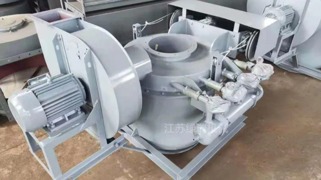
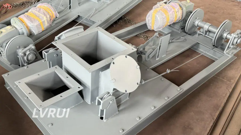
Practical selection guide for dust-free loading spouts used in cement plants, fly ash terminals, truck loading stations and bulk powder handling systems
What Is a Loading Spout?
How to choose loading spout depends first on understanding what the equipment actually does.
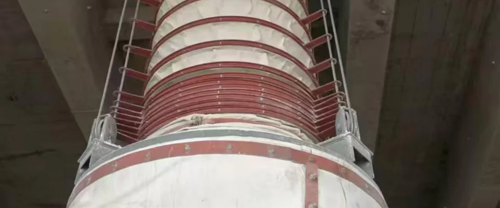
A loading spout is a telescopic bulk loading device installed below a silo, hopper, conveyor discharge point or storage bin. It guides dry bulk material into a truck, tanker, railcar, ship, barge or stockpile while reducing dust emission and material spillage.
In cement and fly ash handling systems, the loading spout is usually used at the final discharge point. Its job is not only to move material downward, but also to control dust, reduce free-fall distance, improve loading accuracy and protect the surrounding working area.
Common names include:
- Loading spout
- Telescopic loading spout
- Loading chute
- Telescopic chute
- Loading bellows
- Dust-free loading spout
Why Loading Spout Selection Matters
A wrong loading spout can create practical problems on site:
- Heavy dust during truck loading
- Material loss around the loading bay
- Slow loading speed
- Poor connection with tanker inlet
- Frequent sleeve damage
- Overfilling or inaccurate loading
- High maintenance around the discharge point
- Poor integration with dust collectors and flow control gates
For fine powders such as cement, fly ash and lime powder, dust control is especially important. OSHA notes that combustible dust hazards can occur when fine particles are dispersed in air under certain conditions, so dust containment and proper equipment design should not be treated as optional.
Quick Answer: How to Choose Loading Spout Equipment
To choose loading spout equipment correctly, engineers should confirm the material type, bulk density, loading capacity, receiving vehicle, discharge height, dust control requirement and control mode before finalizing the design.
For cement and fly ash applications, dust sealing and dust collection are usually more important than simply increasing chute diameter.
How to Choose Loading Spout Equipment: 7 Key Factors
1. Material Characteristics
The first step is confirming the material.
Different materials require different loading spout designs:
| Material | Main Concern | Recommended Design Focus |
|---|---|---|
| Cement | Fine dust, high airflow sensitivity | Enclosed spout with sealing cone and dust extraction |
| Fly ash | Very fine powder, easy dust escape | Dust-free telescopic loading spout |
| Lime powder | Dust and possible moisture sensitivity | Sealed sleeve and corrosion-resistant parts if needed |
| Mineral powder | Abrasion and dust | Wear-resistant contact parts |
| Clinker | Abrasive and heavier particles | Strong chute body and wear-resistant liners |
| Grain / fertilizer | Dust, flowability, hygiene or corrosion | Open or enclosed type depending on loading object |
For cement and fly ash, do not only ask for the spout diameter. You should confirm bulk density, flowability, moisture content, temperature and dust control requirement.
This is why how to choose loading spout equipment must always start from material behavior rather than only from spout diameter or price.
2. Loading Object
The receiving object decides the loading spout type.
| Loading Object | Suitable Loading Spout Type | Typical Application |
|---|---|---|
| Cement tanker | Enclosed truck loading spout | Cement plant bulk truck loading |
| Fly ash tanker | Enclosed dust-free loading spout | Power plant or ash terminal loading |
| Open truck | Open truck loading spout | Sand, fertilizer, grain, mineral material |
| Railcar | Railcar loading spout | Bulk terminal or railway loading station |
| Ship / barge | Ship loading spout or barge loading spout | Port terminal and export loading |
| Stockpile | Stockpile loading spout | Open discharge and pile formation |
If the receiving vehicle is enclosed, a sealing cone and dust extraction interface are usually needed. If the receiving point is open, the focus shifts to dust skirt design, drop height control and material spreading.
3. Loading Capacity
Loading capacity affects the spout diameter, chute structure, lifting system and dust collection airflow.
Before quotation, confirm:
- Required capacity in t/h
- Material bulk density
- Loading time per truck or vessel
- Silo outlet size
- Upstream feeding equipment capacity
- Whether the system runs continuously or intermittently
A high-capacity loading spout must be matched with the upstream flow control gate, conveyor, air slide conveyor or silo discharge system. If the upstream feeding is unstable, the loading spout alone cannot solve loading fluctuation.
4. Silo Outlet Height and Travel Distance
The vertical distance between the silo outlet and the receiving inlet determines the telescopic travel length.
You should provide:
- Silo outlet height
- Truck or tanker inlet height
- Required lifting stroke
- Installation space
- Whether different vehicle heights need to be handled
Too short a travel distance causes dust escape and material splashing. Too long a travel distance increases cost, structural load and maintenance difficulty.
5. Dust Control Requirement
Dust control is one of the most important selection points.
For cement, fly ash and other fine powders, a dust-free loading spout should normally include:
- Outer dust sleeve
- Sealing cone or dust skirt
- Dust collection interface
- Proper connection with bag filter or dust collector
- Optional level sensor
- Good sealing at the discharge point
HSE guidance for dusty cargoes also emphasizes reducing dust generation, using enclosed handling systems where practical and maintaining dust control equipment properly.
For port terminals and dusty bulk cargo handling, the UK Health and Safety Executive also recommends reducing dust generation, using enclosed handling systems where practical, and maintaining dust control equipment properly.
6. Sleeve and Contact Material
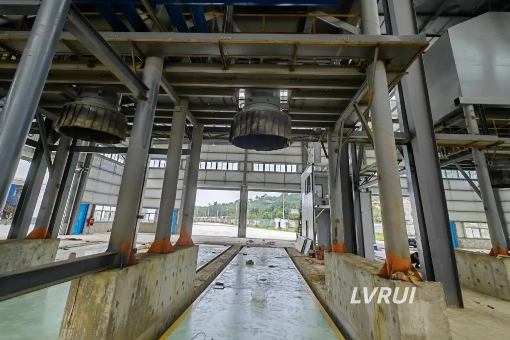
The sleeve and contact parts should match the material condition.
For abrasive materials such as clinker, limestone, slag and mineral powder, wear-resistant liners may be needed. For corrosive or moisture-sensitive materials, stainless steel or special fabric may be considered.
For cement and fly ash, the outer sleeve must balance flexibility, dust sealing and service life.
7. Automation Level
A basic loading spout can be manually operated, but many modern bulk loading systems require semi-automatic or automatic control.
Common options include:
- Electric winch
- Limit switch
- Level sensor
- Control cabinet
- PLC signal interface
- Dust collector linkage
- Emergency stop function
For high-frequency truck loading stations, level detection and automatic stop can reduce overfilling risk and improve loading efficiency.
Loading Spout Selection Checklist
This checklist helps buyers understand how to choose loading spout equipment before requesting a quotation from the supplier.
Before selecting a loading spout, prepare these details:
| Required Information | Why It Matters |
|---|---|
| Material name | Determines dust, abrasion and flow behavior |
| Bulk density | Affects capacity and chute size |
| Required capacity | Determines spout diameter and system design |
| Loading object | Decides enclosed or open type |
| Silo outlet height | Determines telescopic travel distance |
| Outlet size | Affects connection design |
| Dust control requirement | Determines sleeve, sealing and filter connection |
| Working environment | Indoor, outdoor, port or plant conditions |
| Control mode | Manual, semi-automatic or PLC-compatible |
| Material temperature | Affects sleeve and contact part selection |
Loading Spout Type Selection Guide
| Application | Recommended Type | Selection Notes |
|---|---|---|
| Cement tanker loading | Enclosed truck loading spout | Use sealing cone and dust extraction |
| Fly ash truck loading | Dust-free telescopic loading spout | Strong dust control is required |
| Open truck loading | Open truck loading spout | Use dust skirt and drop height control |
| Railcar loading | Railcar loading spout | Focus on positioning and repeatability |
| Ship loading | Ship loading spout | Requires longer travel and stronger structure |
| Barge loading | Barge loading spout | Suitable for river terminals and bulk ports |
| Stockpile loading | Stockpile loading spout | Controls drop height and material spread |
If the receiving vehicle, material type and dust control level are different, how to choose loading spout equipment will also change, even when the required loading capacity is similar.
Loading Spout vs Ordinary Open Chute
| Comparison Item | Ordinary Open Chute | Loading Spout |
|---|---|---|
| Dust control | Weak | Better dust containment |
| Loading accuracy | Lower | More controlled discharge |
| Vehicle compatibility | Limited | Adjustable travel distance |
| Material loss | Higher spillage risk | Reduced material loss |
| Automation | Usually manual | Can use sensors and PLC control |
| Suitable materials | Coarse or low-dust materials | Cement, fly ash, powder and bulk solids |
| Maintenance | More cleaning around loading area | Cleaner loading station |
For cement and fly ash, a loading spout is usually more suitable than an ordinary open chute because fine powder easily becomes airborne during discharge.
Common Mistakes When Choosing a Loading Spout
Many loading problems happen because buyers ask only for price, but do not clearly understand how to choose loading spout equipment for their actual material and loading condition.
Mistake 1: Only Confirming Diameter
Diameter is important, but it is not enough. Capacity, bulk density, vehicle type, travel distance and dust extraction must be checked together.
Mistake 2: Ignoring Dust Collection
For cement and fly ash loading, dust collection should be considered at the design stage. Adding it later may be more difficult and less effective.
Mistake 3: Using the Same Spout for Every Material
Cement, clinker, fly ash, fertilizer and grain do not behave the same. Abrasion, dustiness, flowability and moisture sensitivity all affect the final design.
Mistake 4: Forgetting Upstream Flow Control
A loading spout needs stable feeding. Flow control gates, conveyors, air slide systems or silo discharge equipment should be selected together with the loading system.
Mistake 5: Underestimating Installation Height
If the telescopic travel is wrong, the spout may not seal properly with the tanker inlet or may not reach the loading point.
Practical Example: Cement Truck Loading Spout Selection
This example shows how to choose loading spout equipment for a typical cement truck loading station where dust control and stable discharge are both required.
Project condition:
- Material: Cement powder
- Loading object: Bulk cement tanker
- Required capacity: 120 t/h
- Silo outlet height: 6.5 m
- Main concern: Dust-free truck loading
- Operation mode: Semi-automatic
Recommended solution:
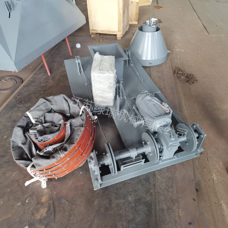
An enclosed telescopic loading spout with sealing cone, dust extraction interface, electric lifting system, limit switch and optional level sensor. The system should be integrated with a dust collector and upstream flow control gate to maintain stable material discharge and cleaner truck loading.
This type of loading spout is suitable for cement plants, grinding stations, fly ash terminals and bulk powder loading stations.
Summary
Accurate loading spout selection starts with one practical question: how to choose loading spout equipment that matches the material, loading object, capacity and dust control requirement.
Choosing the right loading spout is not only a product selection decision. It is a system decision.
For cement, fly ash and bulk powder handling, engineers should evaluate material characteristics, loading capacity, receiving vehicle type, silo outlet height, dust control requirement, sleeve material, automation level and upstream feeding stability.
A properly selected loading spout helps reduce dust emission, improve loading efficiency, lower material loss and create a cleaner bulk loading operation.
FAQs About how to choose loading spout
How to choose loading spout equipment for cement powder?
To choose loading spout equipment for cement powder, confirm the cement bulk density, required loading capacity, tanker inlet size, silo outlet height, dust control requirement and automation level. For cement tanker loading, an enclosed dust-free loading spout with sealing cone and dust extraction interface is usually recommended.
What is the best loading spout for fly ash truck loading?
The best loading spout for fly ash truck loading is usually a dust-free telescopic loading spout. Fly ash is very fine and easily becomes airborne, so the spout should include an outer dust sleeve, sealed discharge outlet and connection to a dust collection system.
What information is needed to choose loading spout equipment correctly?
To choose loading spout equipment correctly, provide material name, bulk density, loading capacity, silo outlet height, receiving vehicle type, travel distance, outlet size, dust control requirement, working environment and control mode.
What is the difference between a loading spout and a telescopic chute?
A loading spout and a telescopic chute are closely related. A telescopic chute describes the extendable structure, while loading spout is more commonly used for dust-controlled bulk material loading into trucks, railcars, ships, barges or stockpiles.
Does a cement loading spout need a dust collector?
Yes. For cement loading, a dust collector is strongly recommended because cement powder can easily escape during discharge. A loading spout with dust extraction helps reduce airborne dust, material loss and cleaning work around the loading station.
How does a loading spout reduce dust during bulk loading?
A loading spout reduces dust by guiding material through a telescopic chute, reducing free-fall distance, sealing the discharge area and connecting with a dust collection system when required. This is especially useful for cement, fly ash, lime powder and mineral powder.
What is the difference between an enclosed truck loading spout and an open truck loading spout?
An enclosed truck loading spout is used for tankers or closed trailers and usually connects directly to the vehicle inlet. An open truck loading spout is used for open trucks, railcars or stockpiles and normally uses a dust skirt or flexible sleeve to reduce dust and spillage.
Can one loading spout handle cement, fly ash, grain and fertilizer?
One loading spout can be customized for different dry bulk materials, but the design should be adjusted according to material dustiness, abrasiveness, moisture content, bulk density and temperature. Cement and fly ash usually need stronger dust control than many granular materials.
Why is loading spout selection important for dust-free cement loading?
Loading spout selection is important because cement and fly ash can generate heavy dust during discharge. Understanding how to choose loading spout equipment helps buyers reduce dust emission, improve loading efficiency, prevent material spillage and match the system with dust collectors, flow control gates and silo discharge equipment.
Need a Dust-Free Loading Spout for Cement, Fly Ash or Bulk Powder Handling?
Jiangsu Lvrui Machinery Co., Ltd. provides customized loading spouts, cement bulk loaders and dust-free bulk truck loading systems for cement plants, fly ash terminals, powder handling projects and bulk material loading stations.
Contact LVRUI for a suitable loading spout solution based on your material, capacity, silo height and loading condition.
Email: info@lvrui-conveyor.com
WhatsApp / WeChat: +86-18261998937
Website: https://lvrui-conveyor.com
Versi Bahasa Indonesia
Loading spout adalah perangkat teleskopik untuk memuat material curah seperti semen, fly ash, kapur, mineral powder, grain dan fertilizer ke truk, tanker, railcar, kapal atau stockpile. Pemilihan loading spout yang tepat harus mempertimbangkan jenis material, bulk density, kapasitas loading, tinggi outlet silo, jenis kendaraan, kebutuhan dust control dan sistem kontrol.
Untuk semen dan fly ash, dust-free telescopic loading spout sangat disarankan karena material halus mudah menghasilkan debu saat proses discharge. Desain yang baik biasanya mencakup dust sleeve, sealing cone, dust collection interface, lifting system dan optional level sensor.
LVRUI menyediakan solusi loading spout untuk cement plant, fly ash terminal dan bulk powder handling system.