Long-Distance Air Slide Conveyor: High-Capacity Powder Conveying Guide

What Changes When Conveying Distance and Throughput Increase in Cement and Dry Powder Handling

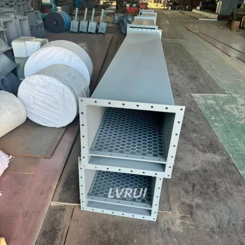
long-distance air slide conveyor for cement powder conveying
Long-distance air slide conveyor sections for enclosed cement and dry powder conveying.

Introduction

Long-distance air slide conveyor applications require more than simply extending a standard conveying chute. As the route becomes longer or the required throughput increases, total elevation loss, air-distribution consistency, venting, feeding stability and downstream restrictions become increasingly important.

A long-distance air slide conveyor still uses the same basic fluidization-and-gravity principle as a shorter air slide, but small problems can accumulate across multiple sections. Uneven feeding, air leakage, poorly coordinated transfer points or restricted discharge can therefore have a greater effect on overall conveying stability.

This guide focuses specifically on the engineering effects of longer conveying distances and higher throughput. Material suitability should be confirmed separately in the Air Slide Conveyor Material Compatibility Guide before a long conveying route is evaluated.


Why Long-Distance Air Slide Conveying Requires Separate Evaluation

The basic conveying principle does not change when an air slide becomes longer, but the effect of system conditions becomes more significant over an extended route.

For a short conveying section, a local air leak, minor feeding fluctuation or small discharge restriction may affect only one part of the line. Over a longer route, similar issues can influence several connected sections and reduce overall conveying stability.

Long-distance applications therefore require closer attention to:

✓ Total elevation loss from inlet to final outlet
✓ Continuity between connected conveying sections
✓ Air distribution over the complete route
✓ Venting at intermediate and final discharge points
✓ Material feeding stability
✓ Transfer and direction-change points
✓ Downstream receiving capacity

The key question is not simply whether an air slide can be made longer, but whether stable fluidization and gravity-assisted flow can be maintained through the complete conveying route.

For the basic conveying mechanism, see the Air Slide Conveyor Working Principle guide.


How Conveying Distance Affects Total Elevation Requirement

A longer air slide route requires more attention to the total elevation difference available between the material inlet and the final receiving point.

Rather than applying one universal slope value, the route should be evaluated from the actual conveying distance, selected inclination, material behavior and plant elevation.

As conveying distance increases, even a moderate downward inclination can create a significant total elevation loss. This can become the practical limitation in plants where the inlet and outlet elevations are already fixed.

Before committing to a long route, confirm:

✓ Total conveying distance
✓ Available inlet-to-outlet elevation difference
✓ Elevation required by downstream equipment
✓ Direction changes or transfer points
✓ Structural restrictions along the route
✓ Whether the complete route can remain continuously downward

If the plant layout cannot provide sufficient elevation difference, dividing the line into more air slide sections does not remove the underlying gravity requirement. Another conveying method may need to be considered for part of the route.


Is There a Maximum Length for an Air Slide Conveyor?

There is no single maximum conveying length that can be applied to every air slide installation.

The practical limit depends on the available elevation difference, material fluidization, required throughput, air distribution, section arrangement, venting, feeding stability and downstream conditions.

A longer system is therefore not evaluated from length alone. The complete route must be checked to determine whether the required material flow can remain stable from the first inlet to the final outlet.

For very long plant routes, the more useful engineering question is:

Can the required elevation, airflow distribution, venting and downstream flow conditions be maintained throughout the entire route?


Air Distribution Over a Long Conveying Route

As conveying distance increases, distributing fluidizing air consistently becomes more important than simply supplying more air from one point.

A long air slide may contain several physical sections or separately controllable air zones. The purpose of zoning is to ensure that different parts of the route can receive stable fluidizing air without relying on one uncontrolled air connection.

Long-route air-distribution planning may consider:

✓ Multiple air inlet points
✓ Separately isolated air branches
✓ Regulating valves for different zones
✓ Accessible pressure-check locations
✓ Air leakage between connected sections
✓ Changes in resistance along the conveying route

Increasing blower output alone is not a reliable solution to poor conveying performance. Excess air cannot compensate for moisture-affected powder, blocked fabric, restricted discharge or major leakage. Research on a full-scale industrial air-slide conveyor also shows that conveying performance is affected by interacting operating conditions rather than airflow alone.

Detailed airflow, pressure loss and blower power should be confirmed separately during equipment sizing. For calculation methods, see the Air Slide Conveyor Power Calculation Guide.

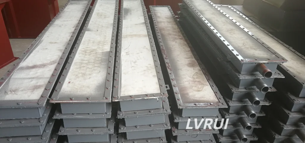
air slide conveyor section with flange and internal support plate
Finished air slide conveyor sections showing the flanged connection and internal support structure.

High-Capacity Air Slide Conveyor Considerations

In a high-capacity long-distance air slide conveyor, increasing throughput affects more than the required airflow. Feeding stability, conveying cross-section, venting, outlet capacity and downstream equipment all become more important as throughput increases.

For high-capacity applications, check the complete material-flow chain:

Feeding Stability

The upstream feeding device should deliver material at a rate the air slide can accept consistently. Large surges can temporarily overload the conveying surface even when the average throughput is within the design range.

Conveyor Cross-Section

Higher throughput may require a larger conveying cross-section or a different conveyor configuration. Simply increasing fluidizing air should not be treated as a substitute for correct conveyor sizing.

Venting Capacity

Higher material throughput can also increase the importance of adequate air release and dust extraction at receiving points.

Outlet and Downstream Capacity

The downstream silo, hopper, packing machine or loading equipment must be capable of accepting the required material flow. A restriction at the final outlet can limit the performance of the complete upstream air slide.

Operating Margin

Preliminary sizing should provide reasonable operating margin rather than relying on a theoretical maximum capacity under ideal material conditions.


Maintaining Flow Continuity Between Sections

Long conveying routes are commonly assembled from multiple air slide sections. Stable operation therefore depends on maintaining smooth material and air-flow conditions across section connections.

At each connection, check:

✓ Alignment between adjoining conveying sections
✓ Clear material passage through the connection
✓ Reliable flange sealing
✓ Continuity of the conveying profile
✓ Air-zone boundaries where applicable
✓ Accessibility for inspection

A poorly coordinated connection can become a local restriction even when the upstream and downstream sections operate correctly on their own.

For long routes, these local effects can accumulate, so section interfaces should be reviewed as part of the complete conveying path rather than as isolated mechanical joints.


Transfer Points and Direction Changes on Long Routes

Long routes may require direction changes, intermediate discharge points or transfers into another conveying section.

Each transition introduces another location where material flow, venting and downstream acceptance must remain stable.

When possible, keep the conveying path simple and avoid unnecessary transfers. Where a direction change or routing device is required, confirm that:

✓ Material can enter the next section without excessive accumulation
✓ The downstream route remains available
✓ Venting is not restricted at the transition
✓ Inspection access is available
✓ The transition does not create an unintended flat or uphill section

For systems that must switch between different destinations, an air slide diverter can be integrated according to the required material-flow route.


Venting Considerations for Long-Distance Air Slides

Venting requirements should be reviewed at transfer points and receiving equipment along a long conveying route.

Fluidizing air entering the air slide eventually reaches the upper material space. If several conveying sections, transfer points or receiving vessels are connected, restrictions in the vent path can affect pressure conditions beyond a single section.

For long routes, review whether:

✓ Intermediate transfer points have a suitable air-release path
✓ Receiving silos or hoppers can vent displaced air
✓ Dust-collection connections are available where required
✓ One restricted vent point can influence an upstream section

Detailed dust-collection system design is outside the scope of this guide. The main objective is to ensure that the extended conveying route does not create unintended pressure restrictions.


Common Long-Distance Air Slide Design Mistakes

1. Extending a Short-Route Design Without Rechecking Total Elevation

A longer route may require significantly more inlet-to-outlet height difference. Length should not be increased without reviewing the complete elevation profile.

2. Treating More Air as the Main Solution

Longer conveying does not mean airflow should simply be increased. Air distribution, leakage, material condition and downstream restrictions must be checked together.

3. Ignoring Section Interfaces

Each additional section introduces another joint, air connection and possible restriction. Poor interfaces can accumulate into an overall conveying problem.

4. Failing to Check Downstream Capacity

A long conveyor cannot maintain stable throughput if the final receiving equipment cannot accept material at the required rate.

5. Ignoring Venting Along the Extended Route

Restricted air release at intermediate or final receiving points can affect upstream conveying stability.

6. Designing Too Close to Maximum Reference Capacity

Changes in powder condition, feeding or operating conditions can reduce available margin. High-throughput systems should not depend only on ideal reference values.


Where Long-Distance Air Slide Conveying Is Most Useful

Long-distance air slide conveying is most practical where fine, fluidizable powder must move continuously between process points that already provide sufficient elevation difference.

Typical situations include:

✓ Cement transfer between elevated process equipment and storage silos
✓ Powder distribution from one upstream source to several downstream destinations
✓ Long silo-to-packing or loading routes with sufficient gravity fall
✓ Extended enclosed powder routes where mechanical conveying elements inside the material path are undesirable

The suitability of an air slide for these applications still depends on actual plant elevation and powder condition. Long distance alone does not make an air slide the preferred conveying method.


When Is a Long-Distance Air Slide Not Practical?

A long-distance air slide may not be practical when:

✓ The plant cannot provide sufficient inlet-to-outlet elevation difference.
✓ The conveying route requires substantial uphill or vertical movement.
✓ The powder cannot maintain stable fluidization.
✓ Frequent transfers or route changes create excessive complexity.
✓ Downstream equipment cannot accept the required throughput.
✓ The process requires positive conveying independent of gravity.

In these situations, pneumatic conveying, screw conveyors, bucket elevators or a combination of different conveying methods may provide a more practical layout.

For applications where gravity-assisted conveying is not practical, see Air Slide Conveyor vs Screw Conveyor.

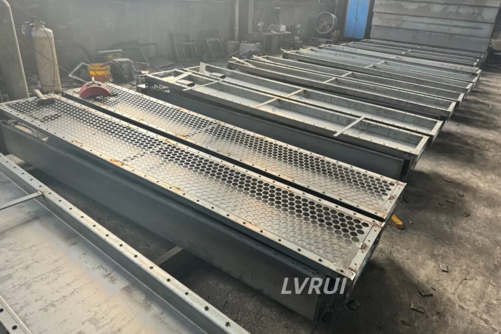
long-distance air slide conveyor sections with perforated support plates
Multiple air slide conveyor sections prepared for a long powder conveying route.

Long-Distance Air Slide Conveyor FAQs

How does elevation loss limit a long-distance air slide conveyor?

As conveying distance increases, the required inlet-to-outlet elevation difference also increases. If the plant cannot provide enough gravity fall while maintaining a continuous downward conveying route, extending the air slide further may become impractical.

Does a longer air slide require more airflow?

Not necessarily in a simple proportional relationship. Long routes may require additional air-distribution zones or inlet points, but airflow and pressure requirements should be determined from actual conveyor sizing and system resistance.

Can several air slide sections be connected for a long conveying route?

Yes. Long routes can use multiple connected sections, but the connections, conveying profile, air distribution and sealing must maintain stable material flow through the complete route.

What limits high-capacity air slide conveying?

Potential limitations include conveyor cross-section, feeding stability, fluidization, venting, outlet capacity and downstream receiving equipment. Capacity should therefore be evaluated across the whole material-flow chain.

When should another conveying method be considered for a long route?

Another method should be considered when sufficient gravity fall is unavailable, the route requires uphill or vertical movement, the material does not fluidize reliably, or the resulting air slide layout becomes impractical.


Conclusion

A long-distance air slide conveyor may not be practical when the complete route cannot maintain the conditions required for stable gravity-assisted conveying.

As distance and throughput increase, total elevation loss, section continuity, air distribution, venting, feeding stability, transfer points and downstream restrictions become increasingly important. These scale-related effects should be reviewed before an existing short-route design is simply extended.

When sufficient gravity fall and stable fluidization are available, multiple air slide sections can be combined into an extended conveying route. Where these conditions cannot be maintained, another conveying method may provide a more practical solution.


Need Help Evaluating a Long-Distance Air Slide Route?

Send LVRUI your conveying distance, inlet and outlet elevations, available height difference, required throughput, number of conveying sections or route changes, upstream equipment, downstream equipment and plant layout drawing.

Based on these conditions, LVRUI can review whether the proposed long-distance air slide route is practical and identify the main factors that require further technical confirmation before final equipment sizing.

Email: info@lvrui-conveyor.com
WhatsApp: +86-18261998937
WeChat: +86-18261998937