Maintenance isolation, lump breaking, rapid shut-off and adjustable flow control explained through a real cement silo-to-tanker loading system
Why Are Four Valves Used?
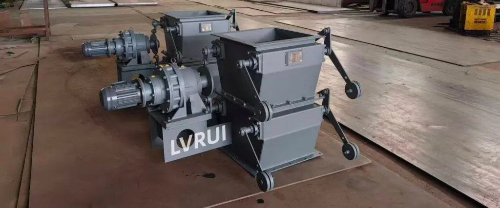
Four valves are used because maintenance isolation, lump breaking, routine shut-off and flow regulation are different operating requirements.
- The manual slide gate isolates the silo for maintenance.
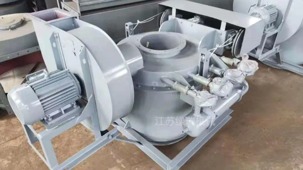
- The electric lump breaker valve reduces hardened cement lumps.
- The pneumatic shut-off gate provides frequent open-close control.
- The motorized flow control gate adjusts the cement feeding rate.
The manual gate normally remains fully open during production. The pneumatic gate starts or stops material flow, while the motorized gate controls how much cement enters the air slide.
Using one device to perform several duties may result in unstable feeding, excessive wear, poor maintenance isolation or downstream blockage. Correctly arranged cement silo discharge valves keep these functions separate.
Equipment Sequence Shown in the Photo
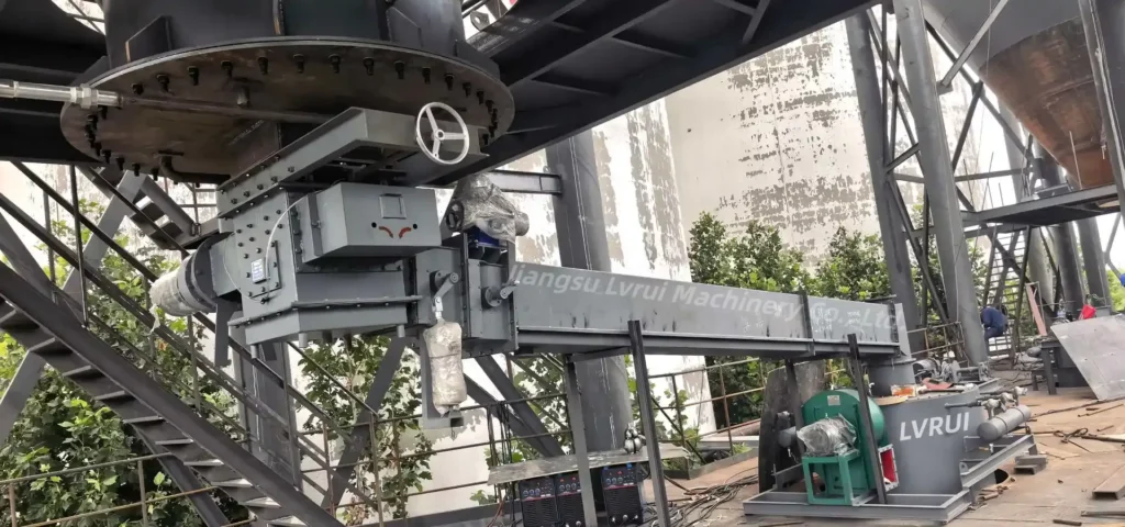
The actual discharge route is:
Silo aeration box → Manual slide gate → Aeration-assisted electric lump breaker valve → Pneumatic shut-off gate → Motorized flow control gate → Air slide conveyor → Integrated cement bulk loader with cartridge dust collector
In this real installation, the cement silo discharge valves are arranged according to four separate duties: maintenance isolation, lump breaking, rapid shut-off and adjustable flow regulation.
Not every cement silo requires exactly this configuration.
However, when a project requires all four functions, using dedicated equipment makes the operating logic clearer and prevents one valve from being used for a duty it was not designed to perform.
Why Cement Silo Discharge Valves Cannot Replace One Another
A valve suitable for maintenance isolation is not necessarily suitable for frequent automatic switching.
A fast on-off gate is not automatically a precise flow-regulating device. A lump breaker can reduce oversized material but should not be treated as the main throttling valve.
The four functions should therefore be evaluated separately:
- Physically isolate stored cement before maintenance.
- Reduce lumps before they reach narrower downstream passages.
- Start or stop material flow during normal production.
- Adjust the discharge rate to match the conveyor and bulk loader.
1. Manual Slide Gate: Maintenance Isolation
The manual slide gate is installed directly below the silo outlet and normally remains fully open during production.
Its main duty is to isolate stored cement when the lump breaker, pneumatic gate, flow control gate or air slide below the silo requires:
- Inspection
- Cleaning
- Repair
- Component replacement
- Extended maintenance
It is not the preferred device for daily flow adjustment.
Manual throttling is difficult to repeat accurately. Leaving the blade partially open for long periods may also cause concentrated wear and material buildup around the reduced opening.
During normal loading, the manual slide gate should therefore remain fully open, allowing the downstream pneumatic shut-off gate and motorized flow control gate to perform production control.
The manual gate is also only one part of the maintenance-isolation arrangement. Before downstream equipment is opened, stored material and all relevant electrical, pneumatic and mechanical energy must be controlled according to the plant’s approved safety procedure and applicable requirements for the control of hazardous energy during maintenance.
Primary function: infrequent maintenance isolation.
2. Electric Lump Breaker Valve: Protecting Downstream Equipment
The aeration-assisted electric lump breaker valve reduces hardened or compacted cement pieces before they enter the downstream gates, air slide inlet and loading equipment.
Its job is material conditioning, not precise flow regulation.
Although cement is a fine powder, occasional lumps may still appear after storage. If a lump enters a narrow transition or a partially opened flow control gate, it may:
- Interrupt cement feeding
- Jam the gate opening
- Accumulate at the air slide inlet
- Increase downstream cleaning requirements
- Cause unstable tanker loading
The rotating breaking elements reduce the lump size so that downstream equipment receives more consistent material.
The aeration assistance helps loosen powder around the discharge area. However, it does not replace the silo aeration system and cannot solve serious cement hardening inside the silo.
If large lumps appear repeatedly, the plant should also check storage time, moisture entry, condensation and silo sealing rather than relying only on the lump breaker.
Primary function: lump reduction and downstream equipment protection.
3. Pneumatic Shut-Off Gate: Routine Open-Close Control
The pneumatic shut-off gate performs the normal start-stop function of the discharge line.
It opens after the air slide conveyor, bulk loader and dust collector are ready. It closes when:
- Tanker loading is complete
- An interlock is activated
- A downstream fault occurs
- The operator stops loading
- An emergency shutdown is required
Pneumatic actuation provides faster response and easier control-system integration than a manual gate.
A standard pneumatic shut-off gate should normally operate in two positions:
- Fully open
- Fully closed
It should not normally remain at an intermediate opening to regulate capacity.
Using an on-off gate as a throttling device may produce unstable feeding because its actuator, blade geometry and position control are primarily designed for switching rather than continuous modulation.
The pneumatic gate also performs frequent production cycles, while the manual slide gate is reserved mainly for maintenance isolation.
Primary function: frequent remote opening and closing.
4. Motorized Flow Control Gate: Adjustable Cement Feeding
The motorized flow control gate controls how much cement enters the air slide conveyor and integrated bulk loader.
Unlike the pneumatic shut-off gate, it is intended to operate at adjustable intermediate openings.
The operator or control system can change its position to match:
- Required loading capacity
- Air slide conveying capacity
- Tanker receiving conditions
- Weighing signals
- High-level signals
- Fast and slow loading stages
For example, the motorized gate may open further during the main loading stage and reduce the flow as the tanker approaches the target level or weight.
This helps prevent sudden cement surges and improves loading-cycle repeatability.
During commissioning, the displayed opening percentage should be compared with the actual mechanical position.
A control screen showing 50% open does not always mean the valve has reached exactly half of its mechanical travel. The actuator stroke, mechanical stops and position feedback should be checked together.
Cement flow is also affected by powder flowability, silo pressure, aeration and downstream resistance. Therefore, a 50% opening does not necessarily produce exactly 50% of the maximum flow rate.
Primary function: adjustable and repeatable flow regulation.
Cement Silo Discharge Valves and Their Functions
The following table shows why the four cement silo discharge valves cannot simply replace one another.
| Equipment | Main duty | Normal production mode | Should not replace |
|---|---|---|---|
| Manual slide gate | Maintenance isolation | Fully open | Daily flow regulation |
| Electric lump breaker valve | Reduce cement lumps | Runs as required | Main shut-off or precise flow control |
| Pneumatic shut-off gate | Rapid on-off control | Fully open or fully closed | Continuous throttling |
| Motorized flow control gate | Regulate feeding rate | Variable opening | Sole maintenance barrier |
The comparison explains why these four devices are not redundant.
If there is no manual isolation gate, maintenance below the silo becomes more difficult because the plant may lack a simple physical barrier against stored cement.
If lumps occur but no suitable lump breaker is installed, the pneumatic gate, flow control gate or air slide inlet may become the first narrow point where oversized pieces accumulate.
If there is no dedicated pneumatic shut-off gate, the motorized flow control gate may be forced to perform every routine production stop, increasing actuator duty and complicating the control sequence.
If there is no adjustable flow control gate, the line may only have full-flow and no-flow states. This makes it harder to match silo discharge with the air slide and control the final tanker-loading stage.
Four valves are not mandatory for every silo. The correct arrangement depends on the actual cement condition, loading capacity, control requirements and maintenance strategy.
The important point is that the four functions must be evaluated separately.
How the Other Equipment Supports the Valve Group
Silo Aeration Box
The silo aeration box loosens cement powder near the outlet and improves flowability.
It helps provide a more stable cement supply to the valve group, but it does not accurately determine the discharge rate. Aeration improves powder movement; the motorized flow control gate regulates how much material enters the downstream system.
Air Slide Conveyor
The air slide conveyor receives regulated cement from the valve group and transfers it toward the loading point.
Stable inlet feeding is important because a sudden uncontrolled surge can temporarily overload the air slide, while insufficient feeding prevents it from reaching the required conveying capacity.
Integrated Cement Bulk Loader
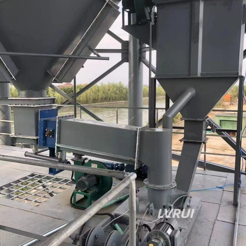
The integrated cement bulk loader combines tanker loading with a local cartridge dust collector.
When cement enters the tanker, displaced air carries fine powder upward. The integrated cartridge filter captures this dust close to the loading point.
Compared with a separate remote dust collector, the integrated arrangement can reduce external ductwork and save installation space beneath or beside the silo.
These supporting devices complete the cement silo-to-tanker loading process, but they do not replace the four valve functions.
Recommended Start-Up and Shut-Down Logic
Correct sequencing of the cement silo discharge valves is essential because material should enter the line only after the downstream conveying and dust-control equipment is ready.
A practical start-up sequence is:
- Position the tanker and lower the loading unit.
- Start the integrated cartridge dust collector.
- Start the air slide blower and confirm conveying air.
- Start silo aeration and the lump breaker as required.
- Confirm that the manual slide gate is fully open.
- Open the pneumatic shut-off gate.
- Open the motorized flow control gate gradually.
This follows a basic operating principle:
Prepare the downstream conveying and dust-control equipment before allowing cement to enter the line.
For normal shutdown:
- Reduce and close the motorized flow control gate.
- Close the pneumatic shut-off gate.
- Allow the remaining cement to clear from the air slide and bulk loader.
- Stop the lump breaker and silo aeration as required.
- Stop the air slide blower after the conveying section is clear.
- Keep the cartridge dust collector operating briefly before final shutdown.
The exact sequence must follow the project’s electrical design, sensors, interlocks and site operating procedures.
Common Function-Matching Mistakes
Using the Manual Slide Gate for Daily Flow Adjustment
This produces poor repeatability and uses a maintenance-isolation device for a production-control duty.
Using the Pneumatic Shut-Off Gate as a Throttling Valve
A standard on-off gate may not provide stable intermediate control or repeatable flow regulation.
Using the Flow Control Gate as the Only Maintenance Barrier
An adjustable production valve should not automatically be assumed to provide the same isolation function as a dedicated manual gate.
Expecting the Lump Breaker to Control Loading Capacity
The lump breaker conditions the material. The motorized flow control gate regulates the feeding rate.
Opening the Valves Before the Air Slide Is Ready
Cement may accumulate at the air slide inlet before sufficient conveying air is established.
Starting Material Flow Before Dust Collection
The first cement surge can displace dusty air from the tanker before the integrated filter is operating.
Cement Silo Discharge Valves FAQs
Why is the manual slide gate normally kept open below a cement silo?
The manual slide gate is mainly used to isolate stored cement during downstream maintenance. During normal production, it usually remains fully open, while the pneumatic shut-off gate handles routine start-stop control and the motorized flow control gate regulates the cement feeding rate.
What is the difference between a pneumatic shut-off gate and a motorized flow control gate?
A pneumatic shut-off gate normally operates fully open or fully closed to start or stop cement discharge. A motorized flow control gate can remain at adjustable intermediate positions to regulate the amount of cement entering the air slide conveyor or loading system.
Can a motorized flow control gate be used as the only maintenance isolation valve?
It should not automatically be treated as the only maintenance barrier. A flow control gate is primarily designed for production regulation. The final maintenance-isolation arrangement must follow the equipment design, stored-material risk and the plant’s approved safety procedure.
Does every cement silo discharge line need a lump breaker valve?
No. A lump breaker is mainly required when hardened cement lumps may enter the discharge line or when downstream gates, transition sections and air slide conveyors need protection from oversized material. The decision should be based on actual cement condition and maximum lump size.
Why is the lump breaker installed before the flow control gate and air slide conveyor?
Installing the lump breaker upstream reduces oversized material before it reaches narrower or partially opened passages. This lowers the risk of the flow control gate becoming jammed and helps prevent large cement lumps from accumulating at the air slide conveyor inlet.
How should cement silo discharge valves be arranged?
In the system shown, the typical sequence is:
Manual slide gate → Electric lump breaker valve → Pneumatic shut-off gate → Motorized flow control gate → Air slide conveyor
The final arrangement depends on cement condition, required capacity, maintenance access, installation height and control requirements.
Conclusion
The four cement silo discharge valves in this loading line are not redundant. Each device performs a different task that supports safe maintenance, stable material flow and controlled tanker loading.
The manual slide gate isolates the silo for maintenance. The electric lump breaker valve reduces oversized cement pieces. The pneumatic shut-off gate starts and stops routine discharge. The motorized flow control gate regulates the cement feeding rate.
Their duties are different and should not be confused.
When coordinated with silo aeration, an air slide conveyor and an integrated cement bulk loader with cartridge dust collection, the complete system provides clearer control, more stable feeding and easier maintenance planning.
Need a Cement Silo Discharge Valve Arrangement?
Jiangsu Lvrui Machinery Co., Ltd. supplies manual slide gates, pneumatic shut-off gates, electric lump breakers, motorized flow control gates, air slide conveyors and cement bulk loading equipment for cement and dry-powder handling systems. When selecting cement silo discharge valves, the supplier must understand both the required material capacity and the separate operating function of each valve.
For equipment selection, please provide:
- Material name and bulk density
- Required loading capacity
- Maximum lump size
- Silo outlet dimensions
- Available installation height
- Air slide size and layout
- Tanker-loading requirements
- Site photos or process drawings
LVRUI can provide equipment drawings, installation drawings and remote technical guidance. On-site installation service is not included.
WhatsApp / WeChat: +86-18261998937
Email: info@lvrui-conveyor.com