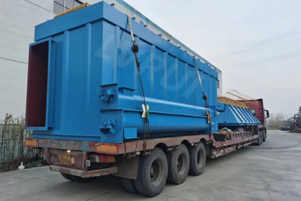
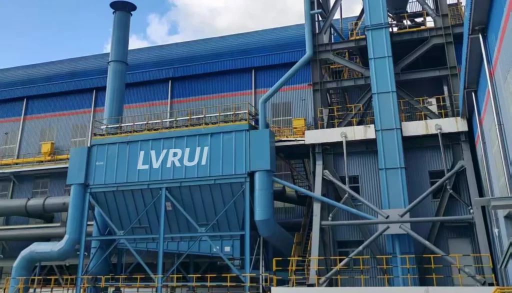
Dust collector hopper discharge methods play an important role in reliable baghouse operation. After filter bags capture dust, the collected powder must be discharged from the hopper and transferred to a suitable receiving point without disrupting the dust collector’s operation. For a technical overview of fabric filter (baghouse) operation, see the U.S. EPA’s guidance.
In cement plants, the discharge arrangement may include a rotary airlock valve, a counterweighted flap valve, a screw conveyor, or a boat-shaped hopper with an air slide conveyor. These options serve different purposes and are not always interchangeable.
This guide compares four common dust collector hopper discharge arrangements, explains their main functions, and identifies the operating conditions that should be considered during equipment selection.
1. Rotary Airlock Valve for Direct Hopper Discharge
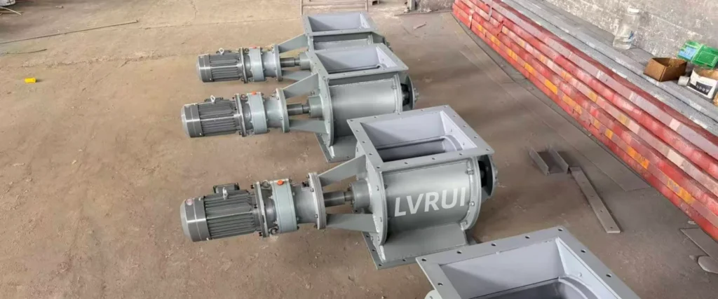
A rotary airlock valve, also known as a rotary feeder or star discharge valve, is commonly installed directly beneath a dust collector hopper.
As the rotor turns, powder moves through the pockets between the rotor blades and discharges into the downstream equipment. This arrangement supports continuous discharge and can provide relatively consistent volumetric feeding when properly selected.
Main advantages
- Continuous powder discharge during normal operation.
- Compact installation beneath a hopper.
- Suitable for integration with downstream conveying equipment.
- Helps limit air leakage between connected equipment when a pressure difference exists.
What should be considered?
The valve must be selected according to the dust characteristics, required discharge capacity, temperature, abrasiveness, rotor clearance, and pressure difference.
A rotary airlock is not a zero-leakage shut-off valve. Its actual air leakage depends on the rotor design, clearances, operating conditions, and wear.
For suitable applications, a rotary airlock valve can provide a practical solution when continuous discharge and controlled feeding are required.
2. Single and Double Counterweighted Flap Valves
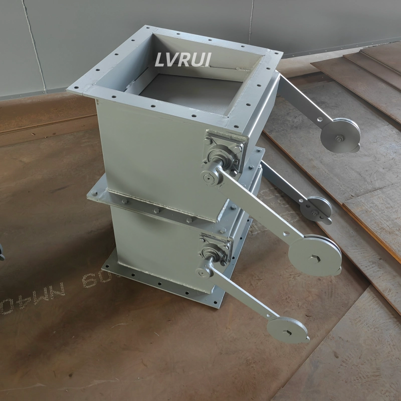
Counterweighted flap valves use gravity and the weight of the flap mechanism to control material discharge. They are commonly used beneath dust collector hoppers where powder can flow downward by gravity.
The appropriate configuration depends on whether the system requires basic discharge control or improved pressure separation.
Single-flap valve
A single-flap valve is suitable for relatively simple gravity discharge applications. Its structure is straightforward, and it does not require an external drive when configured for counterweight operation.
Typical applications include hopper outlets and powder discharge points where the pressure conditions and downstream equipment allow this arrangement.
Double-flap valve
A double-flap valve has two flap plates that operate alternately. Material enters the intermediate chamber through the upper flap and is released through the lower flap after the upper flap closes.
This sequence helps reduce direct air exchange between the upstream and downstream equipment. It is particularly useful when a dust collector operates under negative pressure or when pressure separation is an important design requirement.
Main selection considerations
- Required discharge capacity and operating frequency.
- Pressure difference across the valve.
- Powder flowability and tendency to accumulate.
- Available installation height and maintenance access.
- Required counterweight, pneumatic, or electric operating mode.
A flap valve is primarily a discharge and isolation device. It should not be treated as a precision metering device unless the specific design and control arrangement support that function.
Learn more about single and double flap valves and double-flap valve configurations.
3. Screw Conveyor with a Downstream Discharge Valve
For dust collectors with multiple hoppers, a screw conveyor can collect powder from several discharge points and transport it to a common receiving location.
The typical arrangement is:
Dust collector hoppers → screw conveyor → discharge valve → receiving equipment
The screw conveyor performs the mechanical conveying function. It moves the collected dust along the conveyor trough rather than relying on gravity alone.
Main advantages
- Collects dust from multiple hopper outlets.
- Provides controlled mechanical conveying along a defined route.
- Can transfer powder to a common bin, silo, or downstream handling system.
- Offers flexibility when the layout does not provide enough slope for gravity-assisted conveying.
Why is a discharge valve needed at the conveyor outlet?
In the arrangement described here, the screw conveyor outlet is fitted with either a counterweighted flap valve or a rotary airlock valve, selected according to the downstream process requirements.
The screw conveyor itself should not be assumed to provide reliable pressure isolation. Where the dust collector operates under negative pressure or the downstream equipment has different pressure conditions, the outlet valve must be selected to suit the required pressure separation and discharge function.
A rotary airlock is generally worth considering when continuous discharge or controlled feeding is required. A flap valve may be suitable where gravity discharge and intermittent release meet the process requirements.
What should be considered?
The conveyor capacity must match the expected dust discharge rate. Engineers should also consider the number and spacing of hopper outlets, conveying length, installation inclination, powder characteristics, drive power, and access for maintenance. For additional engineering guidance, refer to the ANSI/CEMA 350-2021 – Screw Conveyors for Bulk Materials standard.
Explore LVRUI’s screw conveyor solutions for cement and dry bulk material handling.

4. Boat-Shaped Hopper with an Air Slide Conveyor
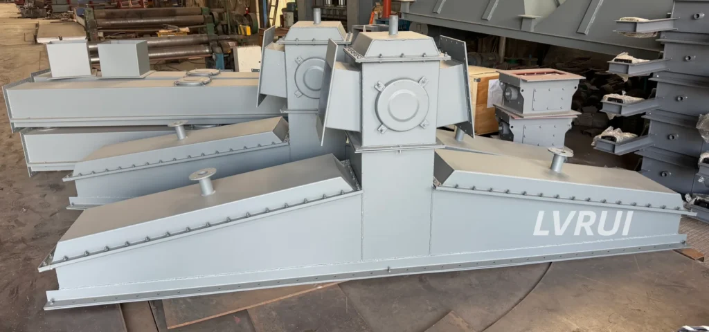
For large baghouses, a boat-shaped hopper combined with an air slide conveyor is an important alternative to arrangements that rely on multiple individual mechanical conveying units.
In this configuration, the hopper collects dust from the filter sections, and the air slide transfers the powder toward a designated discharge point. A counterweighted flap valve is installed at the air slide outlet to control the final discharge and accommodate the downstream process requirements.
The typical arrangement is:
Baghouse hoppers → boat-shaped collection hopper → air slide conveyor → counterweighted flap valve → receiving equipment
In many large dust collection installations, this type of arrangement is increasingly adopted because it can simplify the conveying layout and reduce the number of mechanically driven conveying components.
Main advantages
1. Potential energy savings
An air slide uses low-pressure aeration to fluidize suitable fine powders so that they can move along an inclined conveying surface. Under appropriate conditions, it may consume less energy than a mechanically driven conveying arrangement of comparable duty.
Actual energy consumption depends on conveying distance, slope, aeration requirements, fan efficiency, and the downstream system.
2. Reduced mechanical maintenance
Compared with a system using multiple independently driven screw conveyors, an air slide can have fewer moving mechanical components along the conveying route. This can reduce routine mechanical maintenance when the system is correctly designed and operated.
3. Enclosed powder handling
An enclosed air slide helps contain dry powder during transfer and can reduce dust escape when the connections, inspection covers, and discharge points are properly sealed.
4. Suitability for large dust collectors
A boat-shaped hopper and air slide arrangement can collect dust from multiple sections and convey it toward a common discharge point. This can simplify equipment arrangement and maintenance access in large baghouse installations.
Important design requirements
An air slide is not suitable for every powder or installation layout. The material must have appropriate flow and aeration characteristics, and the conveying route must provide sufficient inclination and suitable connections.
The design should also account for hopper geometry, air distribution, air slide fabric, powder moisture, conveying capacity, and the pressure conditions at the discharge point.
The counterweighted flap valve at the air slide outlet is an important part of the complete arrangement. The air slide transports the powder, while the flap valve controls the final discharge and helps manage air exchange according to the system design.
Learn more about LVRUI’s air slide conveyor systems.
5. Comparison of Dust Collector Hopper Discharge Methods
| Configuration | Main function | Typical application | Key consideration |
|---|---|---|---|
| Rotary airlock valve | Continuous discharge and controlled feeding | Individual hopper outlets | Rotor wear, capacity, and air leakage |
| Single-/Double-Flap Valve | Gravity discharge; pressure separation with double-flap designs | Simple gravity discharge or pressure-sensitive applications | Operating sequence and sealing performance |
| Screw conveyor with a discharge valve | Mechanical conveying and centralized collection | Multiple hoppers with a defined conveying route | Conveyor capacity and outlet valve selection |
| Boat-shaped hopper with air slide and flap valve | Gravity-assisted powder conveying and final discharge | Large baghouse installations with suitable powders and layout | Aeration, slope, air supply, and outlet conditions |
The four dust collector hopper discharge methods serve different functions. Rotary airlock and flap valves control discharge, while screw conveyors and air slides transport powder. A complete system may combine conveying equipment with a separate discharge valve.
6. How to Select the Right Dust Collector Hopper Discharge System
When comparing dust collector hopper discharge methods, engineers should evaluate dust characteristics, required discharge capacity, pressure conditions, conveying layout, and long-term maintenance requirements.
Dust characteristics
Consider bulk density, particle size, moisture content, abrasiveness, temperature, and flowability. These properties affect whether the powder can discharge reliably and whether an air slide is suitable.
Required discharge capacity
The discharge arrangement must handle the expected dust generation and cleaning-cycle discharge without causing excessive accumulation in the hopper.
Pressure difference
Determine whether the dust collector operates under negative pressure and whether the downstream receiving equipment has a different pressure. This affects the selection of the rotary airlock or flap valve.
Number of hoppers and conveying layout
A single hopper may require only a discharge valve. Multiple hoppers may benefit from a common screw conveyor or a boat-shaped collection hopper with an air slide, depending on the available space and conveying route.
Energy and maintenance
Compare the total operating requirements rather than the purchase price alone. Include the power required by drives and air supply equipment, expected wear, inspection access, replacement parts, and routine maintenance.
For an overview of the dust collection equipment itself, see LVRUI’s bag filter solutions for cement plants.
7. Common Mistakes in Dust Collector Discharge Design
Treating all discharge devices as interchangeable
A rotary valve, flap valve, screw conveyor, and air slide have different functions. Equipment selection should reflect the complete material flow path.
Assuming a screw conveyor provides an airlock
A screw conveyor transports powder but should not automatically be relied upon to provide the required pressure isolation. The outlet valve must be selected according to the process conditions.
Installing an air slide without checking the material
Poor flowability, excessive moisture, unsuitable slope, or inadequate aeration can lead to unstable conveying or material accumulation.
Ignoring the final discharge point
The receiving equipment, outlet valve, pressure conditions, and maintenance access should be considered during the initial layout design rather than added after the conveying equipment has been selected.
Selecting equipment by initial cost alone
A reliable system should be evaluated by total operating cost, energy consumption, maintenance requirements, dust containment, and expected service life.
FAQs About Dust Collector Hopper Discharge Methods
What is the best discharge method for a baghouse?
The best option depends on the application. Dust collector hopper discharge methods include rotary airlock valves, single or double-flap valves, screw conveyors with discharge valves, and boat-shaped hoppers with air slides. The right choice depends on dust characteristics, pressure conditions, required capacity, and conveying layout.
Does a screw conveyor need a discharge valve?
For the system arrangement described in this guide, the screw conveyor outlet is fitted with a counterweighted flap valve or rotary airlock valve. The final selection depends on discharge requirements and the pressure conditions of the connected equipment.
Why use a boat-shaped hopper with an air slide under a large baghouse?
This arrangement can collect dust from multiple sections and convey it to a common discharge point. For suitable fine powders and layouts, it can reduce the number of mechanically driven conveying units and simplify maintenance.
Is an air slide always more energy-efficient than a screw conveyor?
No. An air slide can offer energy and maintenance advantages under suitable conditions, but the result depends on the powder, conveying distance, slope, aeration requirements, and fan performance. The complete system should be evaluated before making a comparison.
Why is a flap valve installed at the air slide outlet?
The flap valve controls the final discharge and helps manage air exchange between connected equipment. Its configuration must be selected according to the required discharge capacity and pressure conditions.
Conclusion
The most suitable dust collector hopper discharge methods depend on the material properties, discharge capacity, pressure conditions, equipment layout, and maintenance requirements.
Rotary airlock valves and counterweighted flap valves provide different solutions for hopper discharge and pressure isolation. Screw conveyors are suitable for mechanically collecting and transporting dust from multiple hoppers, with an appropriate discharge valve installed at the outlet. For large baghouses, a boat-shaped hopper combined with an air slide conveyor and a counterweighted flap valve can provide an efficient, enclosed, and low-maintenance conveying arrangement under suitable operating conditions.
As large dust collection systems continue to evolve, boat-shaped hopper and air slide configurations are becoming an increasingly attractive option for suitable cement plant applications because of their potential energy savings, reduced mechanical maintenance, and effective dust containment.
The most reliable solution is not necessarily the one with the fewest components, but the one that matches the material properties, operating conditions, and long-term maintenance requirements of the entire system.
Discuss Your Dust Collector Discharge Requirements
Jiangsu LVRUI Machinery Co., Ltd. supplies equipment for cement plants and dry bulk powder handling, including rotary airlock valves, single and double flap valves, screw conveyors, and air slide conveyor systems.
If you are designing a new baghouse or upgrading an existing dust discharge system, share the following information with our team:
- Dust type and operating temperature.
- Number of hoppers and required discharge capacity.
- Hopper outlet dimensions and available installation space.
- Dust collector and downstream equipment pressure conditions.
- Preferred conveying route and receiving equipment.
LVRUI can help evaluate a suitable equipment configuration according to your material characteristics, layout, and operating requirements.
Contact LVRUI
Email: info@lvrui-conveyor.com
WhatsApp: +86 18261998937
Website: https://lvrui-conveyor.com/