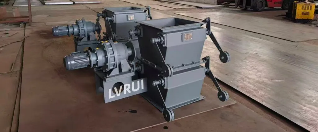
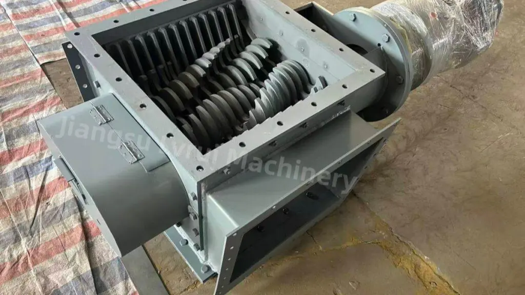
How electric actuators, blade linkages, position feedback and PLC/DCS control work together to operate louver dampers in industrial ventilation and process-air systems

Introduction
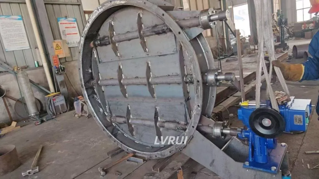
An electric louver damper is a type of industrial damper valve that combines multiple linked blades with an electric actuator, allowing the blade position to be controlled locally, remotely or automatically.
The actuator transfers torque through the damper shaft and linkage system, causing multiple blades to move together. Depending on the actuator and control configuration, the damper may operate as simple open-close equipment or provide intermediate positioning for airflow regulation.
In cement plants, electric louver dampers are commonly considered where large duct sections require remote control, airflow balancing, isolation or integration with a PLC/DCS system.
The electric actuator does not measure airflow by itself. Actual airflow still depends on fan operation, duct resistance, system pressure and process conditions.
This guide focuses on how electric actuation works, how the control modes differ, and what data should be confirmed before selecting a motorized louver damper.
How Does an Electric Louver Damper Work?
An electric louver damper uses an electric actuator to rotate the main drive shaft or operating arm connected to the blade linkage.
A typical operating sequence is:
- The control system sends an open, close or position command to the actuator.
- The actuator produces rotational or linear movement.
- The movement is transferred to the main damper shaft or linkage.
- The linkage moves the connected louver blades together.
- Blade position changes the effective airflow opening across the duct.
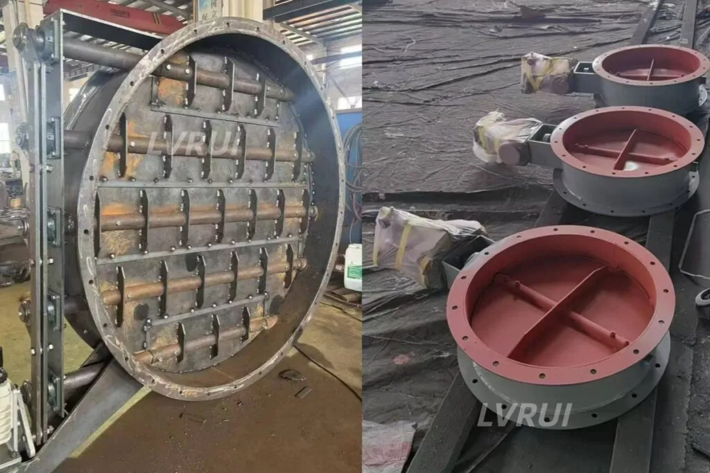
For parallel-blade louver dampers, the blades normally rotate in the same direction.
LVRUI mainly supplies parallel-blade louver dampers as the standard configuration. Opposed-blade arrangements can also be customized when required by the project.
The final blade position depends on the actuator travel, linkage geometry and control signal.
Main Parts of an Electric Louver Damper Control System
| Component | Main Function |
|---|---|
| Louver Blades | Change the effective airflow opening |
| Damper Shafts | Support and rotate the blades |
| Linkage Mechanism | Coordinates movement of multiple blades |
| Electric Actuator | Provides the driving torque |
| Mounting Bracket | Connects the actuator to the damper structure |
| Limit Switches | Confirm open or closed position where required |
| Position Transmitter | Provides intermediate position feedback where required |
| Local Control | Supports local operation during commissioning or maintenance |
| PLC/DCS Interface | Enables remote or automatic control where required |
The actuator should not be selected independently from the damper structure. Blade load, linkage resistance, operating pressure and required operating speed all affect the torque requirement.
Open-Close vs Modulating Electric Louver Damper Control
Open-Close Control
An open-close actuator moves the louver damper between predetermined operating positions.
Typical uses include:
duct isolation;
equipment interlocking;
starting or stopping airflow through a branch;
switching between operating conditions.
Limit switches can be used to confirm whether the damper has reached the required end position.
Modulating Control
A modulating actuator can position the blades between fully open and fully closed positions.
This allows the damper to adjust duct resistance according to a control command.
Depending on the actuator and plant control system, a signal such as 4–20 mA may be used for position commands and feedback.
However, actuator position should not be treated as a direct measurement of airflow. If accurate process airflow is required, the damper should operate together with suitable airflow, pressure or process feedback.
PLC and DCS Integration
Electric louver dampers can be integrated into a plant control system when remote or automatic operation is required.
Typical control functions may include:
remote open-close command;
intermediate position command;
open and closed position feedback;
continuous position feedback;
alarm or fault signal;
interlock with fan or process equipment.
The exact I/O arrangement depends on the selected actuator and control philosophy.
For example, a damper may be prevented from opening until the corresponding fan is running, or the fan may be prevented from starting until the damper reaches a required position.
Interlock logic should be defined according to the process sequence rather than assumed as part of the damper itself.
Why Position Feedback Matters
Remote control is more reliable when the control system can confirm the actual damper position.
Basic systems may use:
open limit switch and closed limit switch to confirm the two end positions.
For modulating operation, an actuator may also provide continuous position feedback.
Position feedback can help operators confirm whether:
the actuator received the command;
the blade linkage moved correctly;
the damper reached the required position;
a mechanical or actuator fault may be preventing movement.
However, position feedback confirms damper position, not actual airflow volume.
How to Select Electric Actuator Torque
Electric actuator torque should be selected according to the actual mechanical load of the louver damper.
Important factors include:
- damper dimensions;
- number and size of blades;
- shaft diameter and bearing resistance;
- linkage geometry;
- operating pressure;
- dust buildup;
- required operating speed;
- sealing arrangement;
- temperature;
- operating frequency.
For large louver dampers, linkage resistance and blade synchronization can significantly affect the required torque.
The actuator should include an appropriate engineering margin, but simply selecting the largest available actuator is not always the best approach.
Excessive actuator torque can place unnecessary load on shafts, linkages and blade connections if the mechanical system becomes jammed.
Fail Position and Emergency Operation
The required damper position during a power failure should be considered during control-system design.
Depending on the process, the preferred condition may be:
remain in the last position;
move to a defined safe position using a suitable actuator arrangement;
allow manual override;
or follow a separate emergency shutdown sequence.
The required fail position is project-specific.
It should be confirmed together with fan operation, process safety and ventilation requirements before actuator selection.
Where Are Electric Louver Dampers Used in Cement Plants?
For a broader overview of kiln, preheater, baghouse, mill and clinker cooler airflow applications, see our guide to damper valve selection for cement plants.
Kiln and Preheater Exhaust Ducts
Electric louver dampers can provide remote or modulating control in exhaust-gas duct systems where damper position must coordinate with fan and process conditions.
Actual suitability depends on temperature, gas composition, dust concentration and duct size.
Baghouse and Dust Collection Ducts
Motorized louver dampers can be used to regulate or isolate airflow in large dust-collection branches.
The required control method depends on whether the application needs simple isolation or adjustable airflow balancing.
Clinker Cooler Ventilation
Electric actuation allows remote damper positioning where cooling-air or exhaust-air duct conditions need to be adjusted during operation.
Raw Mill and Cement Mill Ventilation
Motorized dampers may be used in process-air and exhaust systems where damper position is coordinated with fan operation and system pressure.
Large Industrial Ventilation Ducts
For large duct sections, the multi-blade louver structure can provide coordinated airflow control while electric actuation supports remote operation and automation.
Electric vs Manual Louver Damper
| Factor | Electric Louver Damper | Manual Louver Damper |
|---|---|---|
| Operation | Remote or local | Local |
| Position Adjustment | Open-close or intermediate positioning | Manual adjustment |
| Automation | Can integrate with PLC/DCS | Normally not integrated |
| Position Feedback | Available depending on actuator | Normally visual/manual |
| Operating Frequency | Suitable for repeated adjustment | Better for infrequent adjustment |
| Utility Requirement | Electrical power and controls | No actuator power required |
| Typical Use | Automated process duct | Fixed or occasional adjustment |
Electric actuation is preferable where remote operation, frequent adjustment, interlocking or automatic positioning is required. Manual operation may still be suitable where the damper position changes infrequently.
How to Select an Electric Louver Damper
The damper and actuator should be selected as one mechanical and control system.
Before selection, confirm:
| Selection Factor | What to Confirm |
|---|---|
| Duct Dimensions | Width, height, flange or welded connection |
| Airflow | Normal and maximum airflow volume |
| Pressure | Positive/negative pressure and design pressure |
| Temperature | Normal and peak gas temperature |
| Dust / Gas Condition | Dust concentration, abrasiveness, corrosion or gas composition |
| Blade Arrangement | Parallel blade or project-specific opposed blade |
| Control Mode | Open-close or modulating |
| Actuator Power | Available voltage and frequency |
| Control Signal | Dry contact, 4–20 mA or project-specific signal |
| Position Feedback | Limit switches or continuous position feedback |
| Operating Speed | Required opening/closing time |
| Fail Requirement | Last position, manual override or project-specific safe position |
| Installation Space | Actuator, linkage and maintenance clearance |
| PLC/DCS Interface | Required input/output signals and interlocks |
Providing the duct drawing and control philosophy together with the operating data helps avoid selecting the actuator separately from the damper mechanics.
If the project has not yet determined whether a multi-blade louver structure or a single-blade damper is more suitable, see our Butterfly Damper vs Louver Damper comparison.
Standardized damper performance testing can also evaluate characteristics such as operational torque, air leakage and pressure drop. For reference, see ANSI/AMCA Standard 500-D for damper performance testing.
Electric Actuation Does Not Change the Basic Louver Damper Function
Adding an electric actuator changes how the damper is operated, but it does not change the basic airflow-control function of the louver blades.
The damper still controls air, exhaust gas or dust-laden airflow inside a duct.
It should not be treated as a direct cement powder or bulk-solid flow-control valve.
For direct cement, fly ash or other dry bulk-solid discharge, a flow control gate valve should be evaluated when material-flow regulation is required.
Conclusion
An electric louver damper combines a multi-blade airflow-control structure with an electric actuator for remote or automated operation.
The most important design questions are not simply whether the damper is electric, but how the actuator moves the blade linkage, whether the application requires open-close or modulating control, what feedback signals are needed and how much torque the mechanical system requires.
For cement plant applications, duct size, airflow, pressure, temperature, dust conditions, actuator power, control signals and PLC/DCS requirements should be confirmed together before equipment selection.
FAQs About Electric Louver Dampers
Can an existing manual louver damper be converted to electric actuation?
In many cases, yes. Retrofit feasibility depends on the existing shaft, linkage condition, required operating torque, actuator mounting space and mechanical interface. The existing damper should be inspected before selecting an electric actuator.
What happens to an electric louver damper if power is lost?
The result depends on the actuator and control design. Some actuators remain in their last position, while applications requiring a defined fail position may need a suitable fail-safe actuator, backup power or other emergency arrangement. The required condition should be specified during project design.
What can cause the louver blades to move unevenly?
Possible causes include linkage wear, loose connecting arms, shaft misalignment, bearing resistance, dust buildup or mechanical deformation. Uneven blade movement should be corrected before increasing actuator torque.
Can several electric louver dampers be controlled from one PLC or DCS?
Yes. Multiple dampers can be integrated into a centralized control system, but each actuator should have clearly defined commands, feedback signals and interlocks. The control logic should match the operating sequence of the connected fans and process equipment.
Can the actuator be installed away from the damper body?
It may be possible using an extended shaft or mechanical linkage, but the arrangement must maintain alignment and transmit torque reliably. Additional supports and maintenance access may also be required.
What information is needed when replacing only the electric actuator?
Provide the existing actuator model or nameplate data, required torque, power supply, control signal, travel angle, opening or closing time, mounting dimensions, shaft connection and required fail position. These details help determine whether the replacement actuator is mechanically and electrically compatible.
Need Help Evaluating an Electric Louver Damper?
Send us your duct dimensions, airflow volume, operating temperature, pressure condition, dust or gas characteristics, required control mode, actuator power supply and PLC/DCS signal requirements.
LVRUI can review these conditions and help evaluate the louver blade arrangement, actuator torque, control mode, feedback configuration and mechanical interface required for the project.
For full product specifications and commercial selection, see our Louver Damper Valve product page.
Email: info@lvrui-conveyor.com
WhatsApp: +86-18261998937
WeChat: +86-18261998937