How to Install Lump Breaking Equipment Below Silo Outlets, Hoppers and Powder Discharge Points
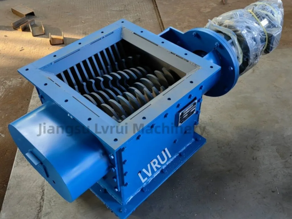
Why Lump Breaker Installation Matters
A lump breaker installation guide is useful because incorrect installation can create problems even when the selected equipment is correct. Poor alignment, weak support, wrong flange connection, limited maintenance space or incorrect control logic may cause unstable discharge, material leakage, equipment wear or unexpected shutdown.
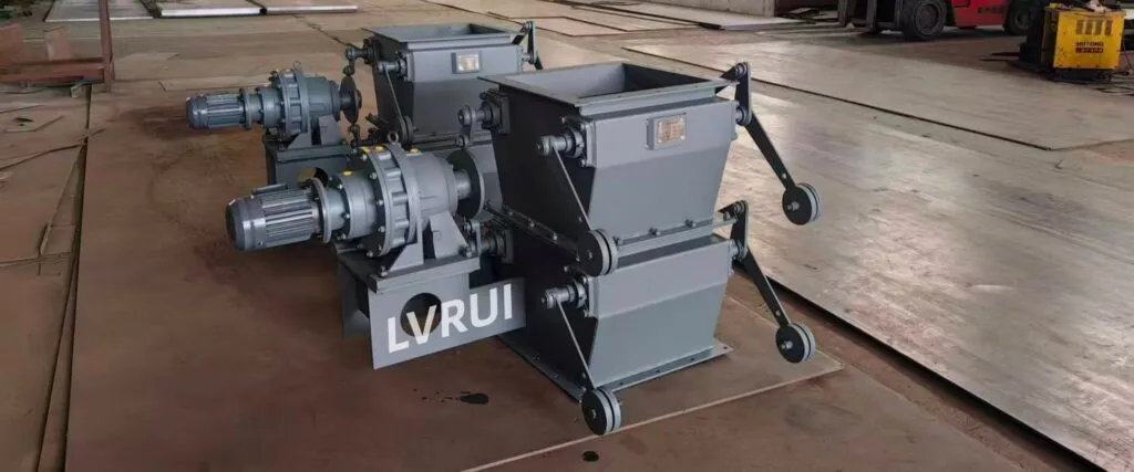
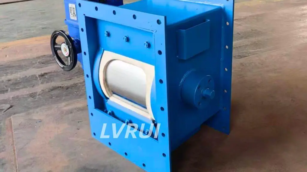
In dry bulk material handling systems, lump breaking equipment is usually installed near the material discharge point. It may be placed below a silo outlet, below a hopper, before a screw conveyor, before an air slide conveyor, before a rotary valve, before a feeder or before a loading system. A practical lump breaker installation guide should evaluate the complete material path instead of treating the machine as an isolated piece of equipment.
The installation should be checked as part of the whole material flow path. The machine must match the upstream discharge point and the downstream equipment at the same time.
Common installation problems include:
√ Flange mismatch
√ Poor alignment with downstream conveyor
√ Weak support structure
√ Insufficient maintenance space
√ Material buildup at the inlet
√ Dust leakage around connections
√ Wrong motor rotation direction
√ Missing interlock with upstream or downstream equipment
√ Difficult blade inspection
√ Unsafe maintenance access
A correct installation reduces blockage risk, improves material flow and makes future maintenance easier.
Step 1: Check the Installation Position
Before installation, confirm where the equipment should be placed.
Following this lump breaker installation guide helps determine whether the selected position can protect the downstream conveyor, valve or loading equipment effectively.
Common positions include:
√ Below silo outlet
√ Below storage hopper
√ Below big bag discharge hopper
√ Before screw conveyor
√ Before air slide conveyor
√ Before rotary valve
√ Before feeder
√ Before mixer
√ Before packing machine
√ Before loading spout or bulk loader
The best position depends on where lumps appear and which downstream machine needs protection. If lumps form inside a silo and reach the outlet, the equipment should be installed before the sensitive downstream machine receives the material.
Do not choose the location only because there is empty space. The installation position should allow stable material entry, smooth discharge and safe maintenance access.
Step 2: Confirm Inlet and Outlet Flange Dimensions
Flange matching is one of the most basic installation checks.
Before installation, confirm:
√ Silo outlet size
√ Hopper outlet size
√ Inlet flange size
√ Outlet flange size
√ Bolt hole position
√ Gasket or sealing requirement
√ Connection height
√ Downstream equipment inlet size
√ Whether an adapter flange is needed
If the inlet is too small, material may accumulate before entering the machine. If the outlet does not match the downstream equipment, powder may leak or build up at the transition point.
For retrofit projects, existing silo outlets and conveyor inlets are often not standard. In this case, the adapter frame or transition chute should be checked before the machine arrives at site.
The flange checks in this lump breaker installation guide are especially important for retrofit projects with non-standard silo outlets and conveyor connections.
Step 3: Check the Support Structure
The support structure must carry the equipment weight, material load, motor load and vibration during operation.
Before lifting and fixing the machine, check:
√ Platform strength
√ Support frame stiffness
√ Anchor bolt position
√ Welding quality
√ Vibration risk
√ Installation height
√ Space for motor and reducer
√ Access for inspection doors
√ Load transfer to silo or steel frame
Do not rely only on the flange connection to carry all forces unless the design allows it. If the support is weak, the machine may vibrate, misalign or cause stress at the flange.
For heavy-duty applications, the support structure should be reviewed together with the silo bottom, downstream conveyor and maintenance platform.
Step 4: Align the Machine with Downstream Equipment
Alignment is a critical part of installation.
The outlet should align with the downstream conveyor, valve, feeder or chute. Poor alignment may cause material spillage, uneven feeding, local buildup and faster wear.
Check these points:
√ Inlet centerline
√ Outlet centerline
√ Downstream conveyor inlet position
√ Shaft orientation
√ Material flow direction
√ Motor side clearance
√ Reducer maintenance space
√ Transition chute angle
√ Whether material can fall freely into the next machine
If the equipment is installed before a screw conveyor, the outlet should feed the conveyor inlet evenly. If it is installed before an air slide conveyor, the discharge should not create a concentrated material pile that disturbs fluidization. If it is installed before a rotary valve, the output size and flow should match the valve inlet.
Correct alignment is one of the most important requirements in a lump breaker installation guide because it directly affects material flow, sealing and equipment wear.
Step 5: Confirm Rotation Direction Before Operation
Before material feeding, confirm the motor rotation direction and rotor movement.
Wrong rotation direction may reduce breaking performance or cause material buildup. It may also overload the motor if the rotor moves against the designed material flow.
Before operation:
√ Jog the motor briefly
√ Check rotor direction
√ Confirm shaft movement
√ Check for abnormal noise
√ Confirm reducer operation
√ Check coupling or chain drive
√ Confirm blade clearance
√ Make sure no tools or foreign objects remain inside
Do not start material feeding before confirming mechanical rotation.
Step 6: Connect Electrical Control and Interlock
The machine should not operate independently from the rest of the discharge system.
For safer operation, the control logic should consider:
√ Upstream gate status
√ Downstream conveyor running signal
√ Motor overload protection
√ Emergency stop
√ Local control box
√ Central control room signal
√ Rotation direction confirmation
√ Start-up sequence
√ Shutdown sequence
√ Inspection door safety switch if required
A typical sequence is:
- Start downstream conveyor or receiving equipment
- Start lump breaking equipment
- Open upstream gate or start material feeding
- Stop upstream feeding first
- Allow remaining material to clear
- Stop lump breaking equipment
- Stop downstream conveyor
This sequence helps prevent material from filling the machine or conveyor inlet during start-up and shutdown. The control sequence recommended in this lump breaker installation guide helps prevent material from entering the machine before downstream equipment is ready.
Step 7: Apply Safety Isolation Before Inspection
Installation and inspection must not be done while the equipment can start unexpectedly.
Before opening inspection doors, checking blades, adjusting bolts or cleaning material buildup, the power supply should be isolated and locked according to the site safety procedure. OSHA describes lockout/tagout as procedures used to disable machinery or equipment and prevent hazardous energy release during servicing and maintenance.
Important safety checks include:
√ Stop upstream feeding
√ Empty material as much as possible
√ Shut down the machine
√ Isolate electrical power
√ Lock and tag the power source
√ Release stored energy if applicable
√ Confirm the rotor has stopped completely
√ Wait for dust to settle
√ Use proper PPE
√ Do not put hands into the housing without isolation
This section is important because lump breaking equipment has rotating shafts and blades. Maintenance access should be planned carefully before installation.
Before opening the inspection door or cleaning material buildup, operators should follow appropriate lockout/tagout safety procedures to isolate electrical and other hazardous energy sources and prevent unexpected equipment start-up.
Step 8: Run a No-Load Test
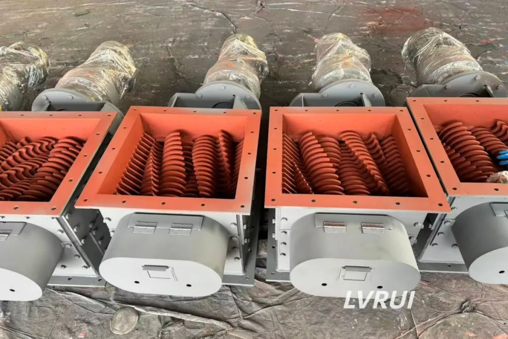
After mechanical and electrical installation, run a no-load test before feeding material.
Check:
√ Motor rotation direction
√ Abnormal vibration
√ Abnormal noise
√ Reducer temperature
√ Bearing temperature
√ Shaft movement
√ Inspection door sealing
√ Bolt tightness
√ Emergency stop function
√ Control signal response
The no-load test helps identify installation problems before material enters the machine. If abnormal vibration or noise appears, stop the test and check alignment, fastening and internal clearance.
A complete lump breaker installation guide should always require a no-load test before cement powder or other bulk material is introduced.
Step 9: Run a Material Test
After the no-load test is normal, run a controlled material test.
Do not feed at full capacity immediately. Start with a small amount of material and observe how it enters and leaves the machine.
Check:
√ Whether material enters evenly
√ Whether lumps are reduced properly
√ Whether material builds up at the inlet
√ Whether the outlet discharges smoothly
√ Whether downstream equipment receives material normally
√ Whether dust leakage appears at the flange
√ Whether motor current remains stable
√ Whether abnormal noise appears under load
√ Whether the output size is acceptable
If the material is too sticky, too wet or too hard, the equipment may need adjustment or a different configuration. Do not judge installation only by whether the machine can rotate.
The material test is the stage where the lump breaker installation guide confirms whether the machine, inlet, outlet and downstream equipment work together correctly.
Step 10: Check Maintenance Access After Installation
Maintenance access should be checked after the machine is installed, not only during layout design.
Operators should be able to inspect and maintain:
√ Motor and reducer
√ Coupling or chain drive
√ Bearings
√ Shaft seals
√ Inspection doors
√ Blades or breaking elements
√ Inlet and outlet transition points
√ Flange bolts
√ Dust sealing points
√ Nearby conveyor or valve connection
If maintenance access is too narrow, routine inspection will be delayed. This can lead to blade wear, material buildup, poor sealing and longer downtime.
Lump Breaker Installation Guide Checklist
| Check Point | What to Confirm | Risk if Ignored |
|---|---|---|
| Installation position | Correct location before downstream equipment | Lumps may still enter sensitive machines |
| Inlet flange | Size, bolt holes and sealing | Material buildup or leakage |
| Outlet flange | Match with conveyor, valve or chute | Spillage and unstable feeding |
| Support frame | Strength, stiffness and anchor bolts | Vibration and misalignment |
| Alignment | Centerline and material flow direction | Wear, buildup and poor discharge |
| Motor direction | Correct rotation before feeding | Low performance or overload |
| Electrical control | Overload, emergency stop and local control | Unsafe operation |
| Interlock logic | Conveyor and gate sequence | Material flooding or blockage |
| Safety isolation | Lockout before inspection | Injury risk during maintenance |
| No-load test | Noise, vibration and signal response | Hidden installation defects |
| Material test | Output size, current and discharge stability | Unstable operation under load |
| Maintenance access | Space for inspection and cleaning | Long downtime and poor maintenance |
This checklist should be used before final acceptance. A machine may be mechanically installed, but not yet ready for stable production if alignment, interlock, sealing or maintenance access is poor.
This lump breaker installation guide checklist should be completed before the equipment is accepted for continuous production.
Common Installation Mistakes
Mistake 1: Installing Too Far from the Problem Point
If the machine is installed too far downstream, lumps may already block a valve, chute or conveyor before they reach it. The installation position should be close enough to protect the sensitive equipment.
Mistake 2: Ignoring Flange Transition Design
A sudden change in inlet or outlet size may create material buildup. Transition chutes should be smooth and properly sealed.
Mistake 3: Poor Alignment with the Conveyor
Misalignment can cause uneven feeding, material leakage and local wear. The outlet should match the conveyor inlet or downstream equipment.
Mistake 4: No Space for Blade Inspection
If there is no room to open the inspection door or remove parts, maintenance will be difficult. This should be checked before installation.
Mistake 5: Starting Material Feeding Before Testing
Material feeding should begin only after no-load testing confirms correct rotation, stable operation and control response.
Mistake 6: No Interlock with Downstream Equipment
If upstream feeding starts before downstream equipment runs, material may accumulate and cause blockage. Interlock logic helps prevent this issue.
Mistake 7: Treating Safety Isolation as Optional
Inspection around rotating equipment must follow site safety procedures. Power isolation, lockout and confirmation of zero movement are necessary before maintenance.
Retrofit Installation in Existing Plants
Many lump breaking machines are installed in existing plants, not only new projects. Retrofit installation is more difficult because the available space, old flange size and downstream equipment layout may already be fixed.
Before retrofit installation, check:
√ Existing silo outlet size
√ Available height under the silo
√ Existing gate or valve position
√ Conveyor inlet location
√ Whether the old support frame can be reused
√ Whether electrical control can be integrated
√ Whether the machine can be lifted into position
√ Whether maintenance doors can open fully
√ Whether dust sealing can be improved
√ Whether production shutdown time is limited
For retrofit projects, photos and drawings are especially important. The installation plan should be confirmed before manufacturing adapter flanges or support frames.
When a Product-Level Page Is More Useful
This article explains installation logic. If the issue is actual equipment selection for cement silo outlet blockage, hardened cement lumps or protection before conveyors and valves, the product page is more useful.
For cement plant applications, a cement silo lump breaker can be selected according to lump size, discharge capacity, silo outlet size, downstream equipment and installation space.
This blog should remain an installation guide. It should not replace the product page, sizing guide or selection guide.
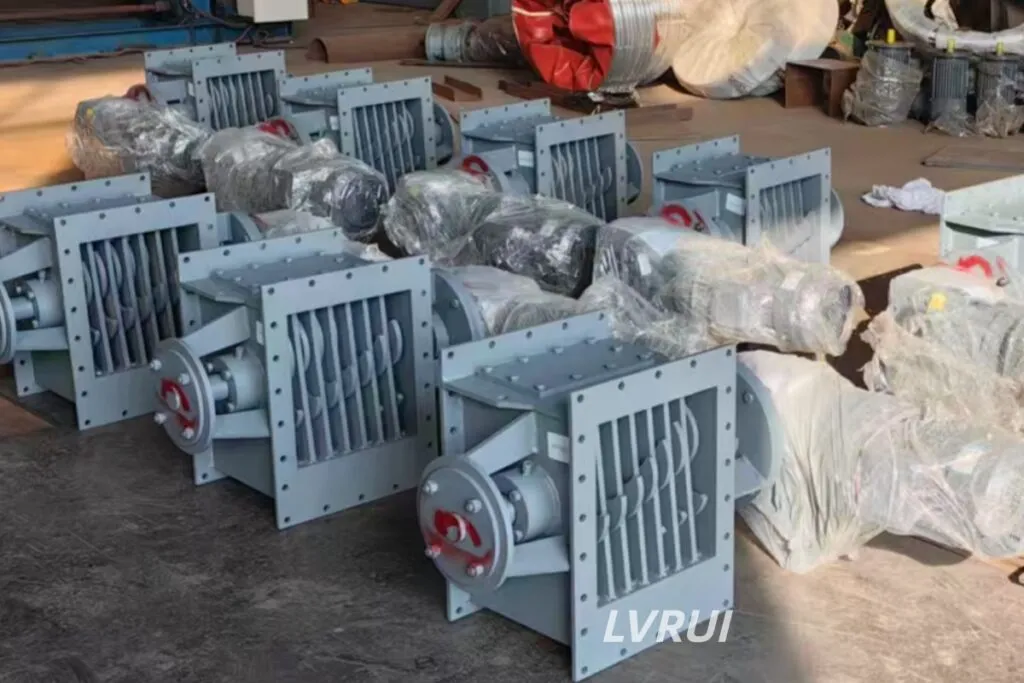
FAQ About Lump Breaker Installation Guide
What does this lump breaker installation guide cover?
This lump breaker installation guide covers installation position, flange dimensions, support structure, equipment alignment, motor rotation, electrical interlock, safety isolation, no-load testing, material testing and maintenance access. These checks should be completed before continuous operation.
Where should lump breaking equipment be installed?
The equipment is usually installed below a silo outlet or hopper, or before a screw conveyor, air slide conveyor, rotary valve, feeder, packing machine or bulk loading system. The correct position should stop oversized lumps before they reach sensitive downstream equipment.
What information should be confirmed before installation?
Before installation, confirm the material type, maximum lump size, required capacity, silo or hopper outlet size, inlet and outlet flange dimensions, available installation height, downstream equipment, motor voltage and maintenance space.
A complete lump breaker installation guide should also include site drawings or photos for retrofit projects.
Why is flange alignment important?
Poor flange alignment may cause material leakage, local buildup, unstable feeding and mechanical stress on the machine housing. The inlet, outlet and downstream connection should follow the same material flow path without unnecessary offsets or sharp transitions.
Should the equipment be interlocked with the upstream gate and downstream conveyor?
Yes. The recommended sequence is to start the downstream conveyor first, then start the lump breaking equipment, and finally open the upstream gate.
The lump breaker installation guide should include this interlock sequence to prevent material from filling the machine when the downstream equipment is not ready.
How can the support structure affect operation?
A weak or flexible support frame may cause vibration, misalignment, loose bolts and stress at the flange connection. The support should carry the machine weight, motor and reducer load, temporary material load and operating vibration.
What should be checked during the no-load test?
During the no-load test, check:
√ Motor rotation direction
√ Abnormal noise
√ Equipment vibration
√ Bearing and reducer condition
√ Shaft movement
√ Bolt tightness
√ Emergency stop
√ Control signal response
√ Inspection door sealing
No material should be introduced until the no-load test is completed successfully.
How should the first material test be carried out?
Start with a small and controlled material flow instead of full capacity. Observe whether material enters evenly, whether lumps are broken properly, whether the outlet discharges smoothly and whether the downstream equipment receives material without blockage.
The motor current, noise, vibration and dust leakage should also be checked during the test.
Can this lump breaker installation guide be used for retrofit projects?
Yes. This lump breaker installation guide is suitable for both new installations and retrofit projects. However, retrofit work usually requires additional checks for existing flange sizes, limited installation height, old support frames, conveyor alignment, lifting access and electrical integration.
How much maintenance space should be reserved?
The layout should provide enough space to inspect or remove the motor, reducer, bearings, shaft seals, blades and inspection doors. Operators should also be able to clean the inlet and outlet without dismantling unrelated equipment.
Maintenance access should be confirmed before the support frame and transition chute are finalized.
What are the most common installation mistakes?
Common mistakes include:
√ Installing too far downstream from the lump source
√ Using mismatched inlet and outlet flanges
√ Relying only on the flange to support the machine
√ Poor alignment with the downstream conveyor
√ Wrong motor rotation direction
√ No interlock with the gate or conveyor
√ Starting material feeding before testing
√ Insufficient inspection and maintenance space
√ Poor sealing around transition points
What safety steps are required before inspection?
Stop upstream feeding, allow the remaining material to clear, shut down the machine and isolate the electrical power. The energy source should be locked and tagged according to the plant safety procedure.
The rotor must be completely stopped before the inspection door is opened or material buildup is removed.
When should the supplier review the installation layout?
The supplier should review the layout when the outlet size is non-standard, installation height is limited, the machine must connect to existing equipment, or the plant requires customized support, transition chutes or control logic.
Following the lump breaker installation guide alone may not be enough when the site layout has unusual space or structural restrictions.
Contact LVRUI for Installation and Powder Discharge Support
If your project requires technical support beyond this lump breaker installation guide, the installation should be reviewed together with the silo outlet, support structure, electrical control and downstream equipment.
Jiangsu Lvrui Machinery Co., Ltd. provides dry bulk material handling equipment for cement plants, grinding stations, fly ash systems, lime powder systems, mineral powder lines and other powder handling applications.
For a proper recommendation, please provide the following information:
√ Material name
√ Maximum lump size
√ Silo or hopper outlet size
√ Installation height
√ Available space
√ Downstream equipment
√ Required capacity
√ Power supply
√ Photos or drawings of the current system
Contact LVRUI:
WhatsApp: +86-18261998937
WeChat: +86-18261998937
Email: info@lvrui-conveyor.com
Simplified Indonesian Version
Lump breaker installation guide membantu memastikan pemasangan alat pemecah gumpalan dilakukan dengan benar di bawah outlet silo, hopper, atau sebelum conveyor, rotary valve, feeder, packing machine, dan sistem loading. Pemasangan yang tepat harus memperhatikan posisi instalasi, ukuran flange, support structure, alignment, arah putaran motor, interlock control, safety isolation, no-load test, dan material test.
Sebelum instalasi, pastikan ukuran inlet dan outlet sesuai, downstream equipment sejajar, ruang maintenance cukup, dan sistem kontrol aman. Setelah instalasi mekanik selesai, lakukan no-load test terlebih dahulu, kemudian material test dengan aliran kecil. Untuk retrofit pada silo lama, foto dan gambar layout sangat penting agar flange adaptor, support frame, dan akses maintenance dapat dirancang dengan tepat.