Comprehensive Guide to Air Slide Conveyor Capacity Calculation
Panduan Lengkap Perhitungan Kapasitas Air Slide Conveyor
Introduction: Why Capacity Calculation Matters
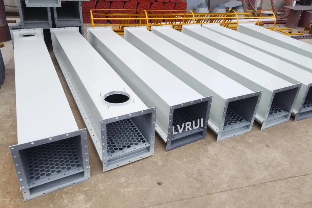
Capacity calculation determines whether an air slide conveyor system operates efficiently and reliably over time. Unlike mechanical conveyors, air slides rely on fluidized material flow driven by gravity and low-pressure air.
Incorrect capacity sizing can cause:
- Unstable flow
- Material accumulation
- Excessive air consumption
- Operational downtime
Proper understanding ensures long-term system stability and efficient powder handling in cement plants worldwide.
For detailed design guidance, see our Air Slide Conveyor Design Parameters Explained.

Key Parameters Required for Capacity Calculation
Material Properties
- Bulk density (static and aerated)
- Particle size distribution
- Moisture content
- Flowability characteristics
Fine powders such as cement, fly ash, and raw meal are ideal for air slide conveying due to their fluidization behavior.
Learn more about powder flow and fluidization principles
Conveyor Geometry
- Air slide trough width
- Effective material bed height
- Total conveying length
Wider air slides allow higher capacities but require more precise air distribution control.
Inclination Angle
The inclination angle directly influences conveying velocity and stability.
- Typical design range: 3°–8°
- Steeper angles increase capacity but reduce flow stability
Air Supply Conditions
- Low-pressure air volume
- Uniform air distribution beneath the aeration fabric
- Stable blower performance
Improper air supply can lead to inefficient fluidization and capacity loss.
Related product: bulk material handling air systems
Basic Capacity Calculation Principle
The conveying capacity of an air slide conveyor can be estimated using the following simplified relationship:
Capacity = Material flow cross-section × Flow velocity × Aerated bulk density
Where:
- Cross-section depends on trough width and bed height
- Flow velocity is affected by air supply and slope
- Aerated bulk density is lower than static density due to fluidization
⚠️ Important: Using static bulk density instead of aerated density is one of the most common causes of capacity miscalculation.
Quick Reference Table: Typical Air Slide Capacities
| Air Slide Width | Typical Capacity (t/h) |
|---|---|
| 150 mm | 10–30 |
| 200 mm | 20–60 |
| 250 mm | 40–100 |
| 300 mm | 80–150 |
| 400 mm | 120–250 |
| 500 mm | 200–500 |
Typical Air Slide Conveyor Capacity Calculation Results for Cement Applications
In cement plants, air slide conveyors are commonly used for:
- Cement discharge
- Fly ash conveying
- Raw meal transport
While capacity varies by design, air slide conveyors are best suited for continuous, moderate-to-high throughput of fine powders.
Related article: What Is an Air Slide Conveyor? Key Components and Working Principle
Common Mistakes in Air Slide Conveyor Capacity Sizing
Many operational issues are caused by incorrect assumptions during capacity calculation:
- ❌ Using static bulk density instead of aerated density
- ❌ Ignoring moisture variation in material
- ❌ Oversizing air supply without flow verification
- ❌ Designing excessive inclination angles
These errors often cause unstable operation and unnecessary energy consumption.
See Common Problems of Air Slide Conveyors (And How to Fix Them)
Capacity Calculation and System Design Integration
Capacity calculation should never be performed in isolation. It must be integrated with:
- Overall system layout
- Aeration fabric selection
- Air supply and blower sizing
Proper calculation ensures efficient system design and long-term operational stability.
Product reference: cement plant material handling systems
When Capacity Recalculation Is Required
Capacity recalculation is recommended when:
- Material type or composition changes
- Moisture content increases
- Conveying distance is extended
- Plant throughput is upgraded
Ignoring recalculation can lead to frequent operational interruptions.
From an engineering perspective, proper air slide conveyor capacity calculation is essential to balance conveying efficiency, air consumption, and long-term system stability in cement and bulk powder handling applications.
Practical Example of Air Slide Conveyor Capacity Calculation for a 150 t/h Cement Line
Project Data:
- Material: Portland Cement
- Capacity: 150 t/h
- Bulk Density: 1.2 t/m³
- Air Slide Width: 300 mm
- Length: 28 m
- Inclination: 7°
Result: The conveyor successfully transported 150 t/h cement with stable fluidization and low energy consumption.
FAQs About Air Slide Conveyor Capacity Calculation
What is the typical cement air slide conveyor capacity for bulk powder handling?
The typical cement air slide conveyor capacity ranges from 10 to 500 tons per hour, depending on conveyor width, material characteristics, aeration efficiency, and system design. In modern cement plants, air slide conveyors are commonly used for continuous bulk powder handling applications such as cement, fly ash, and raw meal transport.
How do engineers perform air slide conveyor capacity calculation in cement plants?
Air slide conveyor capacity calculation is typically based on material flow cross-section, conveying velocity, and aerated bulk density. Engineers must also consider conveyor width, inclination angle, air supply volume, and aeration fabric performance to achieve reliable conveying results in cement plant applications.
Which factors have the greatest impact on air slide conveyor capacity?
The most important factors affecting air slide conveyor capacity include aerated bulk density, particle size distribution, material moisture content, conveyor slope, and air distribution uniformity. Even small variations in these parameters can significantly affect conveying performance and capacity.
How does material density affect air slide conveyor capacity calculation?
Material density directly influences air slide conveyor capacity calculation because heavier materials require different fluidization conditions. Engineers should always use aerated bulk density rather than static bulk density when sizing an air slide conveyor for cement or bulk powder handling systems.
Can air slide conveyors be used for fly ash conveying systems?
Yes. Air slide conveyors are widely used for fly ash conveying systems because fly ash fluidizes easily and can be transported efficiently with low-pressure air. Many power plants and cement plants use air slide conveyors as an energy-efficient solution for fly ash handling.
What is the recommended inclination angle for an air slide conveyor?
For most cement plant air slide conveyor systems, the recommended inclination angle ranges from 4° to 12°. A steeper slope may increase conveying capacity, but excessive inclination can cause unstable material flow and reduced system reliability.
When should air slide conveyor capacity be recalculated?
Air slide conveyor capacity should be recalculated whenever material properties change, moisture content increases, conveying distance is extended, production output is upgraded, or new process equipment is added. Recalculation helps maintain stable operation and prevents capacity bottlenecks.
How can air slide conveyor capacity be increased without replacing the conveyor?
In many cases, air slide conveyor capacity can be improved by optimizing air distribution, upgrading aeration fabric, adjusting material bed depth, improving blower performance, or reducing material moisture. Proper system optimization often increases conveying efficiency without major equipment replacement.
Need a reliable air slide conveyor for cement or bulk powder handling systems?
Accurate air slide conveyor capacity calculation helps engineers select the correct conveyor width, aeration system, and operating parameters for reliable bulk powder handling.
LVRUI provides engineered air slide conveyor solutions designed for stable conveying, low air consumption, and long service life.
📧 Contact us:info@lvrui-conveyor.com
🌐 Website:lvrui-conveyor.com
Versi Bahasa Indonesia
Perhitungan Kapasitas Air Slide Conveyor untuk Industri Semen
Perhitungan kapasitas air slide conveyor sangat penting untuk memastikan aliran material yang stabil dan efisien. Faktor utama yang mempengaruhi kapasitas meliputi densitas material, lebar air slide, sudut kemiringan, serta distribusi udara di bawah kain aerasi.
Dalam industri semen, air slide conveyor banyak digunakan untuk mengangkut semen, fly ash, dan raw meal dengan konsumsi energi yang rendah. Kesalahan umum dalam perhitungan kapasitas adalah menggunakan densitas statis, mengabaikan kadar air material, atau memilih sudut kemiringan yang tidak sesuai.
Dengan perhitungan yang tepat, sistem dapat beroperasi lebih stabil, hemat energi, dan memiliki umur layanan yang lebih panjang.
Untuk informasi lebih lanjut, silakan hubungi tim LVRUI.