A practical restart order for dust collection, conveying, silo aeration, lump breaking and discharge control after shutdown or maintenance

Quick Answer: What Is the Correct Cement Silo Restart Sequence?
For a typical silo-bottom discharge line connected to an air slide conveyor and cement bulk loader, the recommended restart logic is:
- Confirm maintenance is complete and check valve positions.
- Prepare the truck loading point and start dust collection.
- Start the air slide blower or downstream conveyor.
- Restore silo-bottom aeration.
- Start the lump breaker if the system uses one.
- Open the pneumatic shut-off gate.
- Gradually open the motorized flow control gate.
The exact cement silo restart sequence depends on the equipment layout and PLC interlocks, but the core principle is consistent:
Prepare downstream equipment first and release upstream cement last.
Why Restart Order Matters
After a shutdown, the discharge line may not be in the same condition as during normal continuous operation.
Cement near the silo outlet may be more compacted, aeration lines may have been isolated, valves may have changed position during maintenance, and downstream equipment may not yet be ready.
Opening the silo discharge immediately can therefore cause:
- A sudden material surge
- Cement accumulation at the air slide inlet
- Unstable discharge
- Gate or transition blockage
- Excessive dust at the loading point
A controlled restart restores conveying, airflow and material discharge step by step before full capacity is allowed. A controlled cement silo restart sequence restores conveying, aeration and material flow step by step before full discharge capacity is allowed.
Step 1: Confirm the System Is Ready
Before restarting material flow, confirm that maintenance and inspection work have been completed.
Check:
- Access doors and inspection covers
- Electrical and pneumatic connections
- Actual valve positions
- Manual isolation gate position
- Air supply pressure
- Air slide condition
- Dust collector condition
- Downstream loading equipment
- Tools or foreign objects left near the discharge path
If the manual slide gate was closed for maintenance, return it to its normal production position only after the approved isolation procedure has been completed.
Do not rely only on the PLC display. After maintenance, confirm that the mechanical valve position matches the control signal.
For maintenance safety, the plant should also follow its applicable procedures for the control of hazardous energy during maintenance.
These checks provide the starting point for a safe and controlled cement silo restart sequence after maintenance or a long shutdown.
Step 2: Prepare the Loading Point and Dust Collection
If the silo feeds a cement bulk loader, prepare the loading end before cement is released.
Typical checks include:
- Positioning the tanker
- Lowering the loading head correctly
- Confirming the loading connection
- Starting the dust collector
- Checking level or weighing signals
Dust collection should already be operating when cement reaches the tanker because incoming material displaces dusty air from the vehicle.
This is particularly important when the bulk loader uses an integrated dust collector.
The dust collector does not control the cement flow, but it should be ready before the first material surge reaches the loading point.
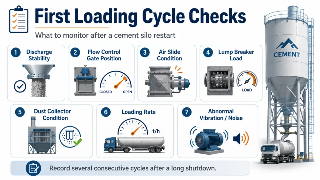
Step 3: Start the Air Slide or Downstream Conveyor
The downstream conveying system should be operating before material enters it.
For an air slide conveyor, start the blower first and confirm that conveying air is available.
Before opening the silo discharge path, check:
- Blower operation
- Air supply
- Major air leakage
- Air slide outlet condition
- Downstream route availability
If cement enters before sufficient airflow is established, material may accumulate at the inlet rather than moving smoothly through the chute.
The same principle applies to screw conveyors and other mechanical conveying equipment:
Start the receiving conveyor before feeding material into it.
Step 4: Restore Silo-Bottom Aeration
After the downstream path is ready, restore silo-bottom aeration.
Confirm that:
- The aeration blower is operating.
- Required air lines are open.
- There is no obvious blockage or leakage.
- Air is reaching the intended discharge zones.
After a long shutdown, cement near the outlet may be more compacted than during normal continuous operation.
Allow the aeration system to establish suitable flow conditions before increasing the discharge rate.
Aeration improves cement flowability, but it should not be used to compensate for a serious outlet blockage or an incorrectly selected discharge opening.
Step 5: Start the Lump Breaker if Required
If the discharge line includes a lump breaker, start it before significant cement flow reaches the downstream gates and air slide.
After a longer shutdown, occasional hardened pieces may leave the silo outlet during the first discharge.
Running the lump breaker first reduces the risk of oversized material reaching:
- Shut-off gates
- Flow control gates
- Narrow transitions
- Air slide inlets
The lump breaker conditions oversized material. It does not regulate the cement loading rate.
Not every cement silo requires a lump breaker; its use depends on the actual material condition and project design.
Step 6: Open the Pneumatic Shut-Off Gate
Once dust collection, downstream conveying, aeration and lump-breaking equipment are ready, the pneumatic shut-off gate can open.
Its main role is routine start-stop control.
During restart, verify:
- Air pressure
- Full actuator travel
- Limit-switch feedback
- Normal opening time
- No mechanical obstruction
A standard pneumatic shut-off gate normally works fully open or fully closed.
It should not normally be used as the main throttling device because its purpose is to start or stop material flow, not to provide continuous capacity regulation.
Step 7: Open the Motorized Flow Control Gate Gradually
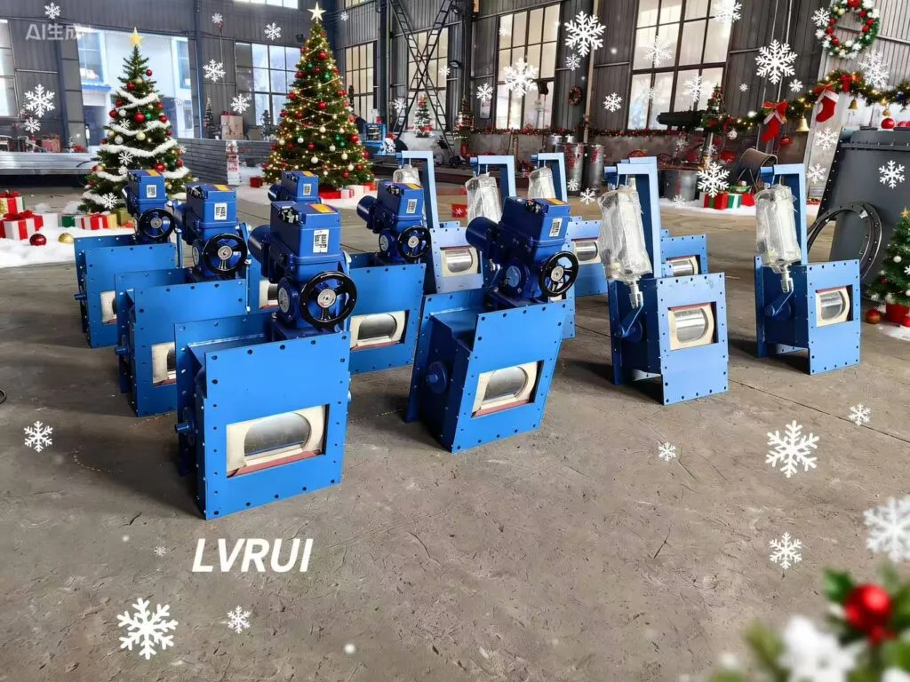
The motorized flow control gate should be the final device used to introduce cement into the prepared downstream system.
Do not immediately command full opening after a long shutdown.
Start with a limited opening and monitor:
- Cement discharge stability
- Air slide condition
- Loading rate
- Dust collector performance
- Tanker response
- Valve-position feedback
If the system remains stable, gradually increase the opening toward the normal operating position.
A motorized flow control gate is useful during restart because it can hold adjustable intermediate positions instead of operating only fully open or closed.
The first loading cycle should therefore be treated as a controlled verification cycle rather than an immediate return to maximum capacity. Gradual flow regulation is the final stage of the cement silo restart sequence before the system returns to normal loading capacity.
Cement Silo Restart Sequence at a Glance
| Restart stage | Equipment or action | Main purpose |
|---|---|---|
| 1 | Maintenance and valve check | Confirm system readiness |
| 2 | Loading point and dust collector | Prepare loading and dust handling |
| 3 | Air slide / downstream conveyor | Establish conveying capacity |
| 4 | Silo-bottom aeration | Restore cement flowability |
| 5 | Lump breaker | Protect downstream passages from lumps |
| 6 | Pneumatic shut-off gate | Release the material path |
| 7 | Motorized flow control gate | Introduce cement gradually and regulate flow |
This is a typical cement silo restart sequence, not a universal PLC program for every cement plant.
Three Common Restart Mistakes
Starting at Full Cement Flow
After a long shutdown, material conditions may have changed.
Begin with a limited flow-control gate opening and increase capacity only after stable conveying has been confirmed.
Trusting the PLC Without Checking the Mechanical Position
A control screen may show that a gate is open even when actuator travel, linkage or limit-switch adjustment is incorrect.
After maintenance, compare the control signal with the actual valve position.
Changing Several Parameters at the Same Time
If discharge is unstable, do not simultaneously increase aeration, change gate opening and adjust conveyor settings.
Change one variable at a time and observe the result. Otherwise, the real cause becomes difficult to identify.
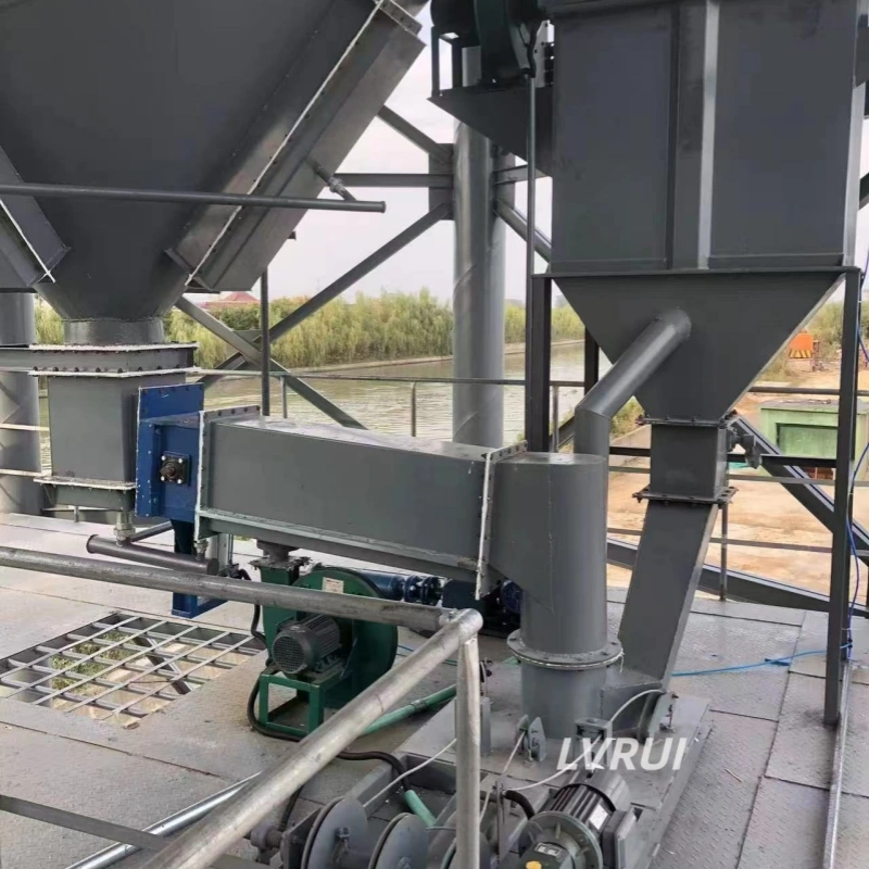
What Should Be Monitored During the First Loading Cycle?
The first loading cycles after shutdown provide useful information about the condition of the complete discharge line.
Monitor:
- Cement discharge stability
- Flow control gate position
- Air slide conveying condition
- Lump breaker load
- Dust collector condition
- Loading rate
- Abnormal vibration or noise
If the shutdown was long or major maintenance was completed, record several consecutive cycles.
This helps distinguish a one-time restart condition from a repeatable equipment problem.
Frequently Asked Questions About Cement Silo Restart Sequence
What equipment should start first when restarting a cement silo?
The downstream conveying and dust-control equipment should generally be ready before cement discharge begins. For an air-slide loading line, the dust collector and conveying airflow are normally established before the silo discharge gates open.
How long should silo aeration run before opening the discharge gate?
There is no universal fixed time. Aeration should run long enough to establish stable airflow and improve cement movement near the outlet. The required time depends on the storage duration, cement condition, silo geometry and aeration-system design.
What should be checked if no cement flows after restart?
Check the actual valve positions, silo aeration, outlet compaction, possible cement lumps and downstream restrictions. Do not simply continue increasing the flow-control gate opening before identifying the real cause.
Can a cement silo restart at full loading capacity immediately?
After a long shutdown or maintenance period, a gradual restart is preferable. Begin with a limited discharge rate and increase capacity only after conveying, aeration, dust collection and material flow remain stable.
Does every cement silo restart require a lump breaker?
No. A lump breaker is relevant only when the system includes one or when hardened cement lumps are a realistic operating risk. It is not mandatory for every silo discharge arrangement.
Is the same restart procedure used after a short stop and a long shutdown?
Not necessarily. A short operational stop may use the normal automatic sequence. After a long shutdown or maintenance period, additional checks of valve positions, aeration, material condition and downstream equipment become more important.
Conclusion
A reliable cement silo restart sequence follows one basic rule:
Downstream first, upstream material last.
For a typical silo-bottom cement loading line, the logic is:
Dust collection → Downstream conveying → Silo aeration → Lump breaking → Shut-off control → Gradual flow regulation
This sequence reduces the risk of releasing cement into equipment that is not ready to receive it.
After a long shutdown, avoid immediately returning every gate to full production settings. Confirm the equipment condition, establish conveying and aeration, and gradually increase cement flow while monitoring the first loading cycles.
Need Help Reviewing a Cement Silo Discharge System?
Jiangsu Lvrui Machinery Co., Ltd. supplies silo aeration equipment, lump breakers, pneumatic shut-off gates, motorized flow control gates, air slide conveyors and cement bulk loading equipment for dry cement handling systems.
For a technical review, please provide:
- Cement type
- Required discharge capacity
- Silo outlet dimensions
- Existing valve arrangement
- Air slide or conveyor specifications
- Loading method
- Current control sequence
- Site photos or process drawings
LVRUI can provide equipment drawings, installation drawings and remote technical guidance. On-site installation service is not included.
WhatsApp / WeChat: +86-18261998937
Email: info@lvrui-conveyor.com