How duct layout, damper position, system resistance and fan interaction affect airflow control in industrial ventilation systems
Airflow Control Challenges for Butterfly Dampers in Industrial Duct Ventilation
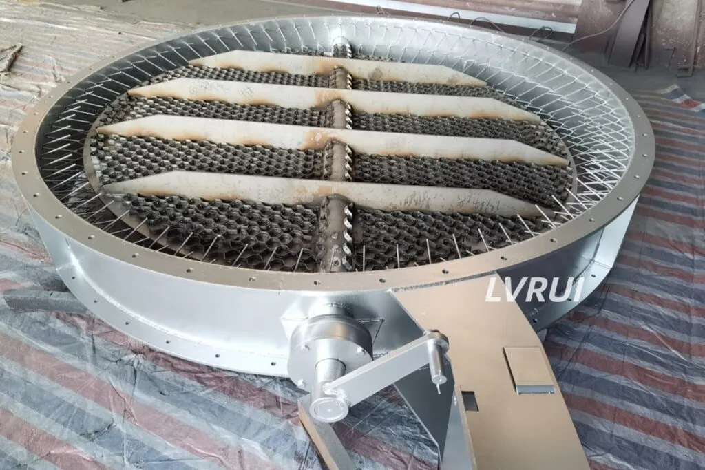
Butterfly dampers for industrial duct ventilation are used to regulate airflow, balance duct branches, and control exhaust or process air in industrial ventilation systems.
Industrial ventilation systems rarely operate under perfectly stable conditions. Changes in fan output, filter resistance, process temperature, dust loading and branch-duct conditions can alter airflow distribution throughout the system.
An industrial damper valve, including butterfly-type designs, provides an adjustable resistance point that can be used to balance airflow between branches, regulate exhaust or process air, and isolate sections of ductwork when required.
However, damper position alone does not determine airflow. Actual flow depends on the interaction between the damper, fan operating point and total system resistance. For this reason, correct installation position and system-level airflow balancing are as important as the damper itself.
How a Butterfly Damper Affects Duct Airflow
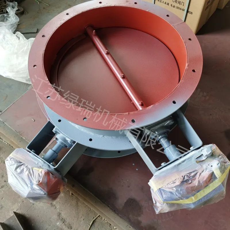
A butterfly damper uses a rotating disc to change the free flow area inside the duct. As the disc moves toward the closed position, local flow resistance and pressure drop increase, reducing airflow through that section of the system.
The relationship between disc angle and airflow is not perfectly linear. The resulting airflow also depends on duct resistance, fan characteristics and conditions upstream and downstream of the damper.
For a detailed explanation of disc rotation, shaft movement and airflow regulation, see our Butterfly Damper Working Principle guide.
Where Butterfly Dampers Are Used in Industrial Ventilation
Main Exhaust Airflow Regulation
Butterfly dampers can be installed in exhaust ducts where airflow must be adjusted according to process demand or changes in downstream resistance.
Branch Duct Balancing
Where one fan serves several duct branches, dampers can introduce controlled resistance into individual branches to help distribute airflow more evenly across the system.
Dust Collection Ducts
In dust extraction systems, butterfly dampers may be used to adjust airflow through selected branches. Damper construction and operating position should account for dust concentration, velocity and possible abrasion.
Process and Cooling Air
Butterfly dampers can also regulate process air, cooling air and ventilation airflow where full-open or partially open operation is required.
For kiln ventilation, preheater, baghouse and other cement-process airflow positions, see our guide to damper valve applications in cement plants.
Duct Isolation
Where the specified leakage performance is acceptable, a butterfly damper may be used to close off airflow to a section of ductwork. However, a standard butterfly damper should not be treated as a positive or airtight isolation device unless it is specifically designed and tested for that duty.
How Damper Position Affects Ventilation Performance
Butterfly damper performance depends strongly on where the unit is installed within the duct system.
Distance from Elbows and Transitions
Elbows, reducers, expansions and tees can produce uneven velocity profiles and turbulence. Installing a damper immediately beside these disturbances may result in uneven loading on the disc and less predictable airflow adjustment.
Where layout permits, provide sufficient straight duct length around the damper and evaluate the local velocity profile rather than relying only on nominal duct airflow.
Position Relative to Fans
Damper placement near fan inlets or outlets requires particular attention because disturbed airflow can affect both fan and damper performance.
The correct arrangement depends on whether the damper is being used for balancing, isolation or process control and on the fan/system configuration.
Duct Alignment
The damper body and shaft should be installed without distortion from misaligned duct flanges. Poor alignment can affect disc clearance, shaft movement and sealing.
Access for Inspection
Allow practical access to the shaft, bearings, actuator and inspection points so that wear, dust buildup and operating movement can be checked during maintenance.
Butterfly Damper and Fan System Interaction
A butterfly damper does not independently set the airflow rate. Closing the damper increases system resistance, which changes the operating point of the fan and therefore changes the resulting airflow.
This means that the same damper angle can produce different airflow rates in two otherwise similar duct systems if their fan curves, duct resistance or filter pressure losses are different.
For airflow balancing, damper adjustment should therefore be evaluated together with actual system pressure and airflow measurements rather than relying only on blade position.
In systems where filter resistance changes during operation, such as dust collection systems, the airflow may also change even when the damper remains at the same position.
Pressure Drop Across a Butterfly Damper
Every butterfly damper introduces some resistance into the duct system. When the disc is near the fully open position, the obstruction is relatively small. As the disc rotates toward a more closed position, the flow area decreases and pressure loss increases.
The actual pressure drop depends on several factors, including:
✓ Duct velocity
✓ Damper size and disc geometry
✓ Disc opening angle
✓ Upstream airflow conditions
✓ Duct geometry
✓ Gas density and temperature
For engineering selection, pressure-drop data should be evaluated under the expected operating condition rather than assuming a fixed value for all butterfly dampers.
Butterfly Damper or Louver Damper for Duct Ventilation?
Butterfly and louver dampers use different blade arrangements and can produce different airflow characteristics in a duct.
A butterfly damper offers a relatively simple single-disc arrangement, while a louver damper uses multiple blades across the duct section. The appropriate design depends on duct dimensions, required control behavior, pressure conditions, leakage requirements and available installation space.
For a detailed comparison, see Butterfly Damper vs Louver Damper.
Actuation for Ventilation Control
Butterfly dampers may be manually, pneumatically or electrically operated depending on the required control method.
For fixed balancing positions, manual adjustment may be sufficient. Systems requiring remote operation or automatic airflow control can use pneumatic or electric actuators.
Actuator selection should consider required torque, operating frequency, control mode and the actual differential pressure acting on the damper.
For complete product configurations and actuator options, see our Butterfly Damper Valve page.
Airflow Balancing in the Complete Duct System
A butterfly damper should be considered as one component of the complete ventilation system rather than as an isolated airflow-control device.
Fan performance, duct dimensions, elbows, branch connections, filters and other pressure losses all contribute to the total system resistance. Changing one damper position can therefore affect airflow elsewhere in a connected duct network.
Industrial exhaust systems may use dampers or other balancing devices to obtain the required airflow through individual branches; see the ASHRAE duct design guidance for broader system-design considerations.
During commissioning, airflow and pressure should be checked at representative operating conditions, and damper positions adjusted according to measured system performance.
Conclusion
Butterfly dampers are widely used in industrial duct ventilation systems for airflow regulation, branch balancing, exhaust control, and duct isolation where the required leakage level allows.
However, damper performance cannot be evaluated by disc position alone. Actual airflow depends on the interaction between the damper, fan operating point, duct resistance, filter condition, and surrounding duct geometry. Installation position, pressure drop, airflow measurements, and system resistance should therefore be considered together during selection and commissioning.
For stable ventilation performance, the butterfly damper should be treated as part of the complete airflow system rather than as an independent control component.
FAQs About Butterfly Dampers for Industrial Duct Ventilation
Does butterfly damper airflow change linearly with disc angle?
No. Disc angle changes the flow area and resistance, but actual airflow also depends on fan performance and the resistance of the entire duct system.
Where should a butterfly damper be installed in a ventilation duct?
A straight and accessible duct section is generally preferable. Avoid locations with severe flow disturbance where practical, such as immediately adjacent to elbows or abrupt transitions, unless the system design has accounted for those conditions.
Can a butterfly damper be used for branch airflow balancing?
Yes. Butterfly dampers can introduce adjustable resistance into individual branches, but the final airflow should be verified by system measurements rather than disc position alone.
Why can the airflow change even when the damper position does not?
Fan operating conditions and system resistance may change because of filter loading, process conditions, duct modifications or other dampers in the network.
Can a butterfly damper be installed near a fan?
It can, but inlet and outlet airflow conditions must be considered. Strongly disturbed or non-uniform flow close to a fan may affect damper loading and airflow behavior.
Is a butterfly damper airtight when fully closed?
Not necessarily. Leakage depends on disc-to-body clearance, sealing design, shaft sealing, differential pressure, temperature, alignment and manufacturing tolerances. Airtight or very-low-leakage performance should only be specified when the damper is designed and tested for that requirement.
Need Help Evaluating a Butterfly Damper for Your Duct System?
If you are evaluating a butterfly damper for industrial ventilation, exhaust gas or dust-laden airflow, send us the basic operating data:
- Duct size and shape
- Airflow rate or duct velocity
- Operating and maximum temperature
- Static or differential pressure
- Dust concentration or gas condition
- Required control method
- Installation drawing or available space
LVRUI can review the operating conditions and help evaluate suitable damper configuration, actuation and installation requirements for the duct system.
Email: info@lvrui-conveyor.com
WhatsApp / WeChat: +86-18261998937