Step-by-step guide to calculating lump crusher capacity, preventing blockages, and optimizing cement silo discharge systems
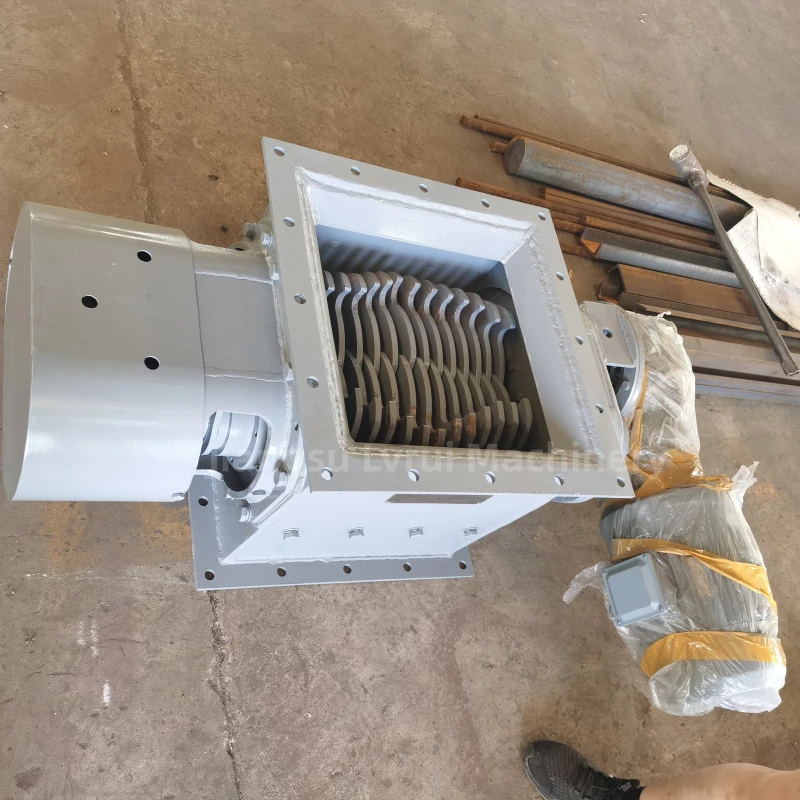
Why a Lump Crusher for Cement Silos Is Critical
In cement plants, bulk storage terminals, concrete batching facilities, and dry mortar production lines, cement is typically stored in silos before being transferred to downstream equipment. Over time, cement can absorb moisture, compact under its own weight, or form hardened lumps. These lumps can block silo outlets, damage rotary valves, disrupt air slide conveyors, and reduce bulk loading efficiency.
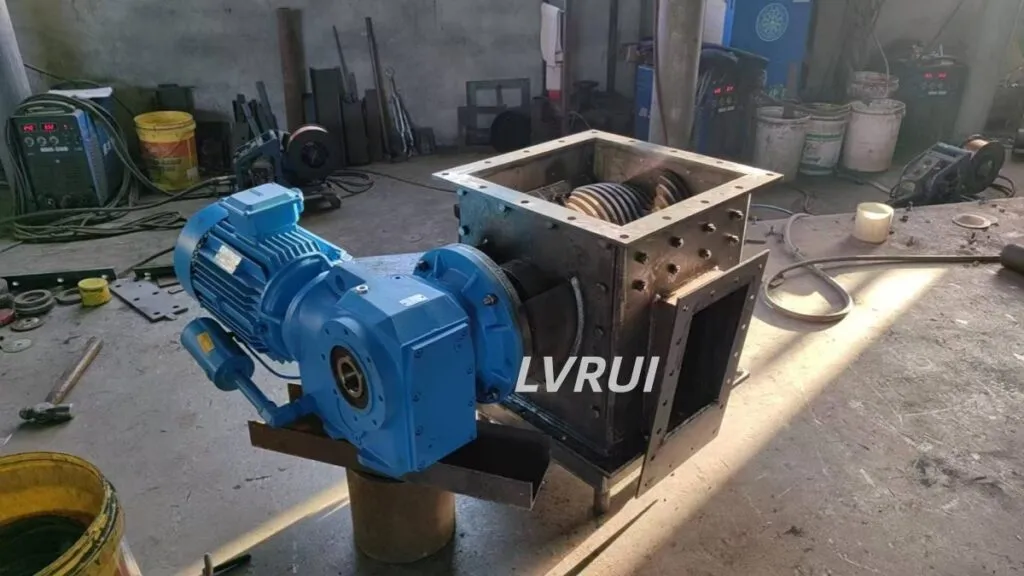
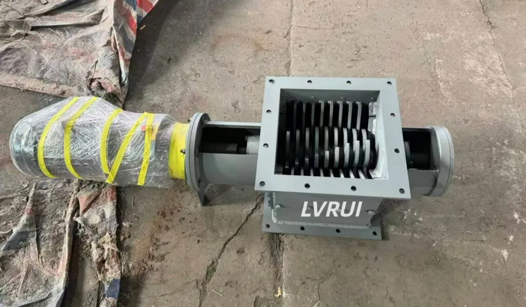
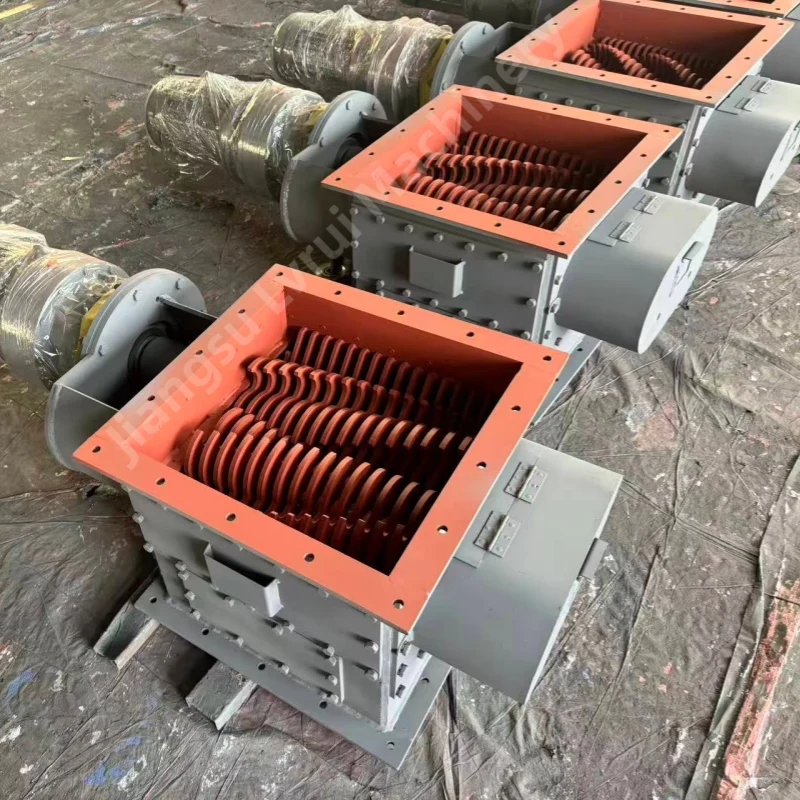
Installing a lump crusher beneath a cement silo ensures continuous material flow, prevents downtime, and protects downstream equipment. This solution is essential in modern plants that require stable production and minimal maintenance costs.
In many modern cement plants, a complete cement silo discharge system includes a lump crusher, flow control valve, and air slide conveyor to ensure stable material flow.
Causes of Cement Lump Formation
Understanding why lumps form helps engineers select the right crusher capacity and configuration.
- Moisture Infiltration – Even minor humidity can trigger cement hydration, resulting in hard lumps.
- Material Compaction – Larger silos (500T–1000T) exert pressure on stored cement, creating denser lumps.
- Temperature Variations – Condensation inside the silo can cause localized cement agglomeration, especially in tropical climates.
- Long-Term Storage – Cement stored for extended periods tends to develop particle bonding, increasing the risk of bridging and arching.
How to Calculate Lump Crusher Capacity
Selecting a crusher based solely on silo volume is a common mistake. Proper sizing depends primarily on discharge rate and material characteristics.
Step 1: Determine Required Throughput
Estimate the maximum material flow per hour.
| Silo Size | Typical Throughput (TPH) |
|---|---|
| 100T | 5–10 |
| 500T | 20–40 |
| 1000T | 40–80 |
Step 2: Evaluate Material Characteristics
- Maximum lump size
- Lump hardness
- Moisture content
- Bulk density
- Storage duration
Step 3: Apply Safety Factor
A common engineering safety margin is 1.25–1.5× to accommodate peak operating conditions.
Example:
Maximum discharge rate = 40 TPH
Safety factor = 1.5
Recommended crusher capacity = 40 × 1.5 = 60 TPH
Recommended Lump Crusher Sizes
100T Cement Silo
- Capacity: 5–10 TPH
- Motor Power: 3–5.5 kW
- Applications: Small batching plants, dry mortar production
500T Cement Silo
- Capacity: 20–40 TPH
- Motor Power: 7.5–15 kW
- Applications: Medium cement terminals, commercial concrete plants
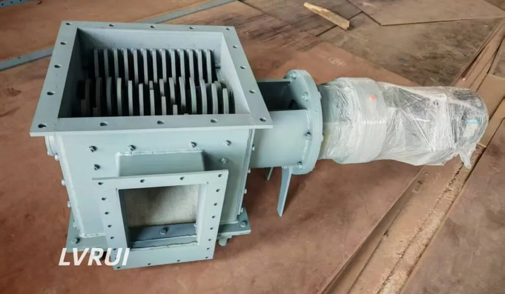
- Preferred Design: Twin-shaft for larger lumps
1000T Cement Silo
- Capacity: 40–80 TPH
- Motor Power: 18.5–30 kW
- Applications: Large cement plants, export terminals
- Design: Heavy-duty twin-shaft industrial crusher
Material Considerations
Different materials require adjusted crusher sizing.
- Cement – Medium-strength lumps; standard crushers sufficient.
- Fly Ash – Absorbs moisture; may require higher torque.
- Clinker – Harder lumps; shaft and rotor strength critical.
- Slag – Particle size affects crusher efficiency.
Installation Best Practices
- Position directly beneath the silo outlet.
- Install upstream of rotary valves, air slide conveyors, or screw conveyors.
- Ensure clearance for maintenance and inspections.
In many cement terminals, the lump crusher is installed upstream of the bulk truck loading system to prevent oversized material from affecting loading efficiency.
Common Selection Mistakes
- Basing capacity solely on silo volume
- Ignoring moisture content
- Underestimating lump size
- Not allowing for future plant expansion
- Selecting low-cost equipment without lifecycle considerations
Benefits of Properly Sized Lump Crusher
- Smooth, uninterrupted cement flow
- Reduced equipment wear
- Lower maintenance costs
- Improved bulk loading efficiency
- Minimized downtime
- Higher plant productivity
Maintenance Best Practices
Daily: Check vibration, motor temperature, discharge consistency
Weekly: Inspect crushing teeth, shaft alignment, remove buildup
Monthly: Lubricate bearings, inspect gearbox, monitor motor current
conveyor equipment standards for industrial lump crusher and cement handling systems
FAQs About Lump Crusher for Cement Silos
How do engineers determine whether a Lump Crusher for Cement Silo is necessary?
A Lump Crusher for Cement Silo is typically recommended when operators experience recurring discharge problems such as bridging, arching, rat-holing, or material blockage at the silo outlet. If large cement agglomerates are entering downstream equipment and causing interruptions, a cement silo lump crusher can significantly improve material flow reliability.
In most modern cement plants, installing a lump crusher is considered a preventive measure rather than waiting for costly production downtime.
What capacity Lump Crusher for Cement Silo is required for a 500-ton silo?
The required lump crusher capacity depends primarily on the silo discharge rate rather than the total storage volume.
For example:
500T silo discharging at 20 TPH → Recommended crusher capacity: 25–30 TPH
500T silo discharging at 40 TPH → Recommended crusher capacity: 50–60 TPH
Most engineers apply a safety factor of 25%–50% when performing lump crusher sizing calculations to ensure stable operation during peak production periods.
Is silo capacity or discharge rate more important when selecting a Lump Crusher for Cement Silo?
Discharge rate is generally more important.
Many buyers assume that a larger silo automatically requires a larger crusher. However, a 1000-ton silo discharging at 20 TPH may require a smaller industrial lump crusher than a 500-ton silo operating at 50 TPH.
The correct approach is to calculate the maximum hourly material flow and then select the crusher accordingly.
Can a Lump Crusher for Cement Silo eliminate bridging and rat-holing problems?
A lump crusher cannot completely eliminate bridging or rat-holing inside the silo itself, but it can significantly reduce the operational consequences.
When combined with:
Air slide systems
Silo aeration devices
Flow control valves
a properly sized cement silo blockage solution can dramatically improve discharge consistency and reduce downtime.
Should a Lump Crusher be installed before an Air Slide Conveyor?
Yes.
An air slide conveyor is designed to transport fine powder efficiently, but it is not intended to handle large hardened cement lumps.
Installing a Lump Crusher for Cement Silo before the air slide conveyor protects the conveying system, improves powder fluidization, and reduces maintenance requirements throughout the cement silo discharge system.
What is the difference between a Lump Crusher and a Hammer Crusher in cement applications?
Although both machines reduce material size, their operating principles are different.
A lump crusher is designed to break soft or moderately hardened agglomerates that form during storage and handling.
A hammer crusher is designed for primary or secondary crushing of larger and harder materials such as limestone, clinker, or aggregates.
For cement silo discharge systems, a lump crusher is usually the more efficient and economical solution.
Can one Lump Crusher serve multiple cement silos?
Yes, provided the system is properly designed.
Engineers must evaluate:
Maximum combined discharge rate
Material characteristics
Feeder arrangements
Maintenance accessibility
In large cement plants, a centralized industrial lump crusher can sometimes serve multiple silos if only one silo is discharged at a time.
Is a Twin Shaft Lump Crusher better than a Single Shaft design?
For most medium and large cement silos, a twin shaft lump crusher offers several advantages.
Benefits include:
Higher throughput capacity
Better handling of large agglomerates
More uniform particle size reduction
Improved operational reliability
Single-shaft units may still be suitable for smaller 100T silos with relatively low discharge rates.
What information should be provided before purchasing a Lump Crusher for Cement Silo applications?
To select the correct equipment, manufacturers typically require:
Silo capacity
Required discharge rate (TPH)
Maximum lump size
Cement bulk density
Moisture content
Installation location
Downstream conveying equipment
Providing accurate data allows suppliers to recommend the most suitable lump crusher sizing and motor configuration.
How can I calculate the correct Lump Crusher capacity for a new cement storage project?
A simplified engineering approach is:
Recommended Crusher Capacity = Maximum Discharge Rate × 1.25–1.5 Safety Factor
For example:
Required discharge rate = 40 TPH
Safety factor = 1.5
Recommended lump crusher capacity:
40 × 1.5 = 60 TPH
This method helps ensure the Lump Crusher for Cement Silo can accommodate peak operating conditions, future production increases, and occasional oversized agglomerates without becoming a bottleneck.
Need help selecting the right Lump Crusher for cement silo?
Contact LVRUI today for customized capacity recommendations based on your silo size, material characteristics, and required discharge rate.
Email: info@lvrui-conveyor.com
Website: https://lvrui-conveyor.com
✅ Get expert quotation and customized solution within 12 hours
✅ Factory direct supply with strict quality control
✅ Professional engineering support from experienced team
✅ Stable delivery for overseas industrial projects
Indonesian Version
Pemilihan lump crusher yang tepat untuk silo semen sangat penting untuk mencegah penyumbatan dan memastikan aliran material lancar. Artikel ini menjelaskan cara menghitung kapasitas crusher untuk silo 100T, 500T, dan 1000T, termasuk tips instalasi, pemeliharaan, dan solusi masalah umum. Dengan informasi ini, manajer pabrik dan insinyur dapat membuat keputusan yang tepat, melindungi peralatan, dan meningkatkan efisiensi produksi.