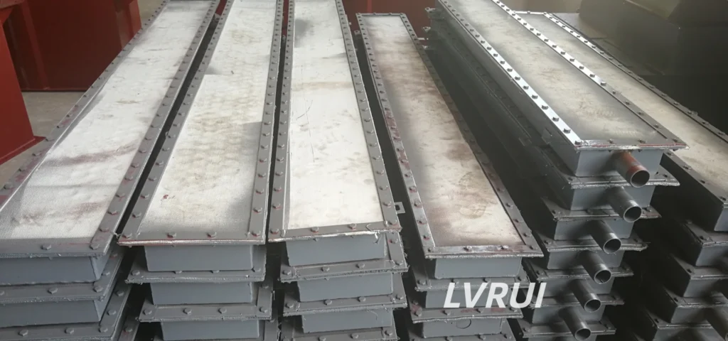
Practical guide to flow control gates for air slide conveyor systems, cement powder discharge, and bulk material flow regulation
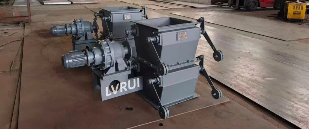
What Are Flow Control Gates in Air Slide Conveyors?
Flow control gates in air slide conveyors are installed to control the discharge rate of fluidized powder materials such as cement, fly ash, raw meal, lime powder, and mineral powder. They are usually mounted at the inlet, outlet, transfer point, or branch discharge section of an air slide conveyor system.
Unlike screw feeders or rotary valves, a flow control gate does not continuously push material by mechanical force. Its main job is to adjust the opening area and control how much powder leaves the air slide conveyor at a given time.
In a cement plant, this small adjustment can make a big difference. If the gate opens too much, the system may experience material surging, unstable discharge, or inaccurate feeding. If the gate opening is too small, material may accumulate inside the air slide and reduce conveying efficiency.
Air slide conveyor system for cement powder handling
Why Flow Control Gates Matter in Cement Air Slide Systems
Air slide conveyors rely on low-pressure air and gravity to move fine powder materials. The conveying fabric allows air to pass through, fluidizing the material layer above it. When the powder is properly fluidized, it flows smoothly along the inclined air slide.
A poorly selected gate can interrupt this balance.
Common problems include:
✔ Sudden cement discharge surges
✔ Uneven feeding to downstream equipment
✔ Powder accumulation at the outlet
✔ Air leakage around the discharge point
✔ Reduced flow control accuracy
✔ Dust leakage during operation
✔ Frequent manual adjustment by operators
For this reason, flow control gates in air slide conveyors should not be treated as ordinary slide gates. They must match the air slide width, outlet size, powder flow behavior, sealing requirement, and automation level of the system.
pneumatic powder transport systems
Typical Applications of Flow Control Gates in Air Slide Conveyors
Flow control gates are commonly used in cement plants, fly ash handling systems, and bulk powder transfer lines.
Typical applications include:
✔ Cement grinding discharge lines
✔ Cement silo feeding and discharge systems
✔ Air slide conveyor outlet control
✔ Raw meal and kiln feed regulation
✔ Fly ash conveying and distribution
✔ Lime powder and mineral powder handling
✔ Bulk material batching systems
✔ Powder transfer points before bucket elevators or screw conveyors
✔ Discharge control before bulk loading systems
In these applications, the flow control gate is not only a shut-off device. It is part of the process control system. Its performance affects feeding accuracy, conveying stability, dust control, and equipment protection.
Flow Control Gate vs Ordinary Slide Gate
Many buyers search for slide gates, flow gates, shut-off gates, or flow control valves and assume they are the same product. In actual air slide conveyor systems, the difference matters.
| Item | Flow Control Gate for Air Slide Conveyor | Ordinary Slide Gate |
|---|---|---|
| Main function | Regulates powder flow rate | Opens or closes material flow |
| Control accuracy | Higher | Lower |
| Suitable for fluidized powder | Yes | Not always |
| Common installation | Air slide inlet, outlet, transfer point | Hopper outlet, chute, general discharge |
| Sealing requirement | Higher, especially in dusty cement systems | Depends on application |
| Automation option | Pneumatic or motorized control | Manual, pneumatic, or motorized |
| Best use | Cement, fly ash, raw meal, fine powders | Granules, general bulk solids, coarse material |
For air slide systems, the gate should be selected based on flow regulation, not just isolation.
Common Types of Flow Control Gates
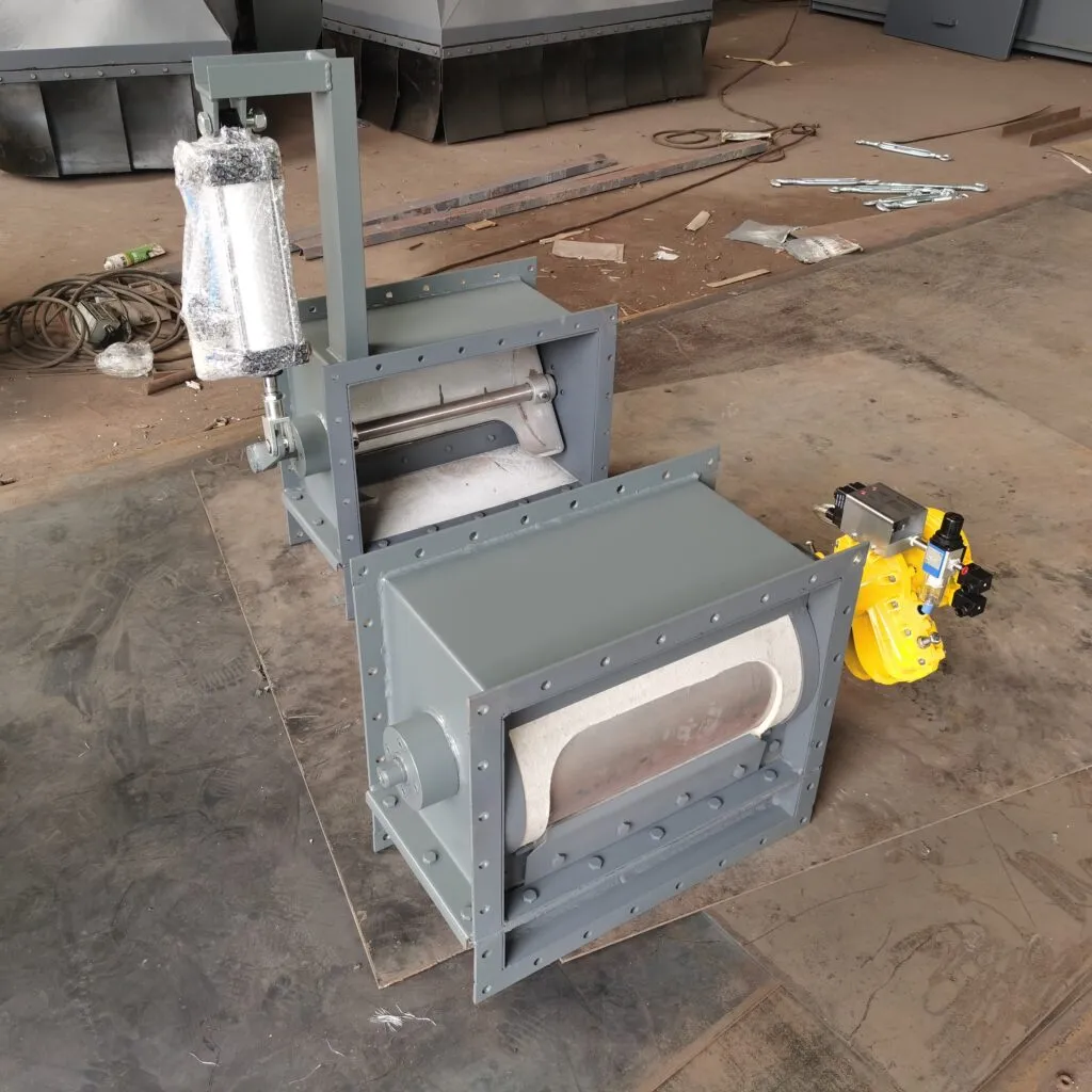
Pneumatic Flow Control Gates
A pneumatic flow control gate uses an air cylinder to open, close, or adjust the gate plate. It is suitable for dusty cement plant environments where fast actuation and simple automation are required.
It is commonly used for:
✔ Frequent open-close operation
✔ Cement silo discharge control
✔ Air slide conveyor outlet regulation
✔ Automated process lines
✔ Dusty powder handling environments
A pneumatic type is often preferred when the plant already has compressed air available.
Pneumatic flow control gate for air slide conveyor
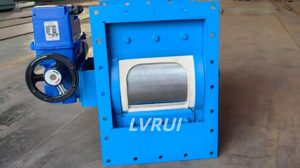
Motorized Flow Control Gates
A motorized flow control gate uses an electric actuator to achieve more precise opening adjustment. It is suitable when the process requires stable positioning, adjustable flow rate, or connection with a control system.
It is commonly used for:
✔ Continuous cement flow regulation
✔ Kiln feed and raw meal control
✔ Central control room operation
✔ Applications requiring adjustable gate opening
✔ Systems where flow rate changes during production
For cement plants that require more accurate flow adjustment, motorized control is usually more suitable than simple on-off control.
Motorized flow control gate for cement plants
Manual Flow Control Gates
A manual flow control gate is suitable for systems where the gate position does not need frequent adjustment. It is simpler, cost-effective, and easy to maintain.
It is often used for:
✔ Maintenance bypass lines
✔ Low-frequency discharge points
✔ Auxiliary powder transfer lines
✔ Small cement or fly ash conveying systems
✔ Backup or emergency shut-off positions
Manual gates are not ideal for processes that require frequent adjustment or remote operation, but they are still useful in many simple powder handling layouts.
Manual flow control gate valve
How Flow Control Gates Improve Air Slide Conveyor Stability
A stable air slide conveyor depends on three things: proper fluidization, correct slope, and controlled material discharge. The flow control gate affects the third factor directly.
When the gate is correctly selected and installed, it can help:
✔ Maintain a stable powder discharge rate
✔ Prevent sudden material flushing
✔ Reduce material accumulation inside the air slide
✔ Improve downstream feeding accuracy
✔ Protect bucket elevators, screw conveyors, and loading equipment
✔ Reduce dust leakage at transfer points
✔ Support automation in cement plant production lines
For example, when cement powder is discharged from a silo into an air slide conveyor, a motorized flow control gate can gradually adjust the opening instead of releasing material suddenly. This helps the downstream conveying system stay stable.
Powder transfer system for bulk material handling
Where Should Flow Control Gates Be Installed?
Flow control gates can be installed in different positions depending on the system layout.
Common installation positions include:
| Installation Position | Main Purpose |
|---|---|
| Air slide conveyor inlet | Control material entering the conveyor |
| Air slide conveyor outlet | Regulate discharge into downstream equipment |
| Silo discharge point | Prevent uncontrolled powder flow |
| Transfer chute | Manage flow between two systems |
| Branch distribution point | Control material flow to different lines |
| Before bucket elevator | Prevent overload and unstable feeding |
| Before bulk loading system | Improve truck loading stability |
The most important rule is simple: install the flow control gate where powder flow needs to be regulated, not merely where a shut-off plate is convenient to place.
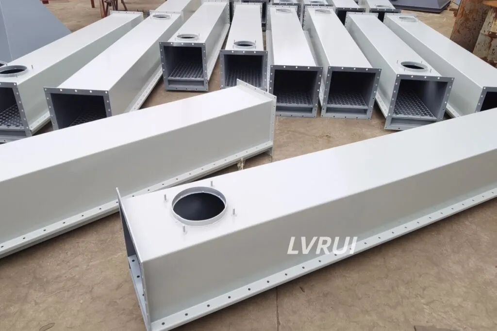
Selection Guidelines for Flow Control Gates in Air Slide Conveyors
When choosing flow control gates in air slide conveyors, engineers should evaluate the whole conveying system, not just the gate size.
Key selection factors include:
✔ Material type: cement, fly ash, raw meal, lime powder, mineral powder
✔ Material condition: moisture, temperature, abrasiveness, flowability
✔ Air slide width and outlet size
✔ Required flow rate and adjustment range
✔ Need for on-off control or proportional control
✔ Pneumatic, motorized, or manual operation
✔ Available compressed air or power supply
✔ Dust sealing requirement
✔ Installation space and maintenance access
✔ Connection with PLC or plant automation system
If the material contains hard lumps or compacted powder, the flow control gate may not solve the problem alone. In that case, a lump breaker should be considered before the material enters the air slide conveyor or downstream system.
Lump breaker for cement silo discharge
Common Mistakes When Selecting Flow Control Gates
Many problems with flow control gates in air slide conveyors come from wrong gate type selection, poor sealing, or mismatch with powder flow behavior.
Common mistakes include:
✔ Using a normal slide gate instead of a flow control gate
✔ Ignoring air leakage around the gate body
✔ Selecting only by opening size, not by flow rate
✔ Using manual gates where automation is required
✔ Installing the gate too far from the actual discharge point
✔ Ignoring material moisture and powder flowability
✔ Failing to consider downstream equipment capacity
✔ Choosing a gate that is difficult to inspect or maintain
For cement and fly ash systems, stable flow control is usually more important than simply making the gate opening larger.
bulk solids flow problems in hoppers and feeders
Flow Control Gate Selection Table
| Application | Recommended Type | Reason |
|---|---|---|
| Cement silo discharge | Pneumatic or motorized flow control gate | Stable discharge and dust control |
| Air slide outlet regulation | Motorized flow control gate | Better opening adjustment |
| Fly ash conveying line | Pneumatic flow control gate | Fast actuation and reliable sealing |
| Raw meal feeding | Motorized flow control gate | Better process control |
| Auxiliary discharge line | Manual flow control gate | Simple and cost-effective |
| Automated cement plant line | Motorized or pneumatic gate | Easy integration with control system |
| Maintenance bypass | Manual gate | Low operating frequency |
This table is useful for procurement teams, engineers, and cement plant operators who need a quick reference when comparing different flow control gate options.
Maintenance Tips for Flow Control Gates
A flow control gate works in a dusty and abrasive environment, so regular inspection is important.
Maintenance checks should include:
✔ Gate plate movement
✔ Sealing surface condition
✔ Air cylinder or actuator operation
✔ Dust leakage around the gate body
✔ Bolts and flange connection
✔ Limit switch or position feedback
✔ Material build-up around the opening
✔ Wear on the sliding plate
If the gate does not open smoothly or the powder flow becomes unstable, the problem should be checked early. Delayed maintenance may cause air slide blockage, inaccurate feeding, or unexpected production stops.
Summary
Flow control gates in air slide conveyors are essential components for cement plants and bulk powder handling systems. They help regulate cement, fly ash, raw meal, and other fine powder materials while maintaining stable fluidized conveying conditions.
For simple on-off control, a pneumatic flow control gate is often enough. For more accurate flow adjustment, a motorized flow control gate is usually a better choice. For low-frequency or auxiliary discharge points, a manual flow control gate can still be practical.
The best selection depends on material characteristics, air slide conveyor layout, flow rate, sealing requirement, automation level, and maintenance access. A correctly selected gate improves powder flow stability, reduces dust leakage, protects downstream equipment, and supports long-term cement plant operation.
FAQ: Flow Control Gates in Air Slide Conveyors
What are flow control gates in air slide conveyors?
Flow control gates in air slide conveyors are devices used to regulate the discharge rate of fluidized powder materials such as cement, fly ash, raw meal, and lime powder. They are commonly installed at air slide inlets, outlets, transfer points, and silo discharge sections.
Why are flow control gates in air slide conveyors important for cement plants?
Flow control gates in air slide conveyors are important because they prevent sudden powder surges, improve discharge stability, reduce dust leakage, and protect downstream equipment. In cement plants, accurate flow regulation helps keep the air slide conveyor system stable and reliable.
Where are flow control gates installed in an air slide conveyor system?
Flow control gates are usually installed at the air slide conveyor inlet, outlet, silo discharge point, transfer chute, or branch distribution point. The best installation position depends on where cement, fly ash, or bulk powder flow needs to be controlled.
What is the difference between a flow control gate and a standard slide gate?
A flow control gate is designed to regulate powder flow rate, while a standard slide gate is mainly used for simple open-close operation. For fluidized powder systems, flow control gates in air slide conveyors provide better control, sealing, and discharge stability than ordinary slide gates.
Should I choose a pneumatic or motorized flow control gate for an air slide conveyor?
Choose a pneumatic flow control gate when the system needs fast open-close operation and simple automation. Choose a motorized flow control gate when the air slide conveyor requires adjustable opening, more accurate powder flow control, or integration with a cement plant control system.
Can flow control gates in air slide conveyors be used for fly ash systems?
Yes. Flow control gates in air slide conveyors are suitable for fly ash conveying systems where stable discharge and controlled powder flow are required. For fly ash, smooth gate movement, proper sealing, and reliable air slide conveyor operation are especially important.
What problems happen if the wrong flow control gate is selected?
The wrong flow control gate may cause unstable discharge, powder accumulation, air leakage, dust emission, inaccurate feeding, downstream equipment overload, or frequent manual adjustment. In air slide conveyor systems, the gate must match the material, flow rate, outlet size, and conveying layout.
How do engineers select flow control gates in air slide conveyors?
Engineers select flow control gates in air slide conveyors by checking material type, moisture content, abrasiveness, air slide width, outlet size, required flow rate, sealing requirement, automation level, installation space, and maintenance access. For cement powder handling, stable flow control and dust sealing are both critical.
Need a reliable flow control gates for air slide conveyors for your cement or powder handling system?
LVRUI focuses on bulk material handling equipment for cement and powder industries, covering discharge, conveying, dust control, and bulk loading systems.
Contact LVRUI today for professional technical support and fast quotation.
✔ Customized flow control gate solutions for cement plants
✔ Proven experience in bulk material handling systems
✔ Fast response and reliable after-sales service
📧 Email: info@lvrui-conveyor.com
🌐 Website: https://www.lvrui-conveyor.com
Versi Bahasa Indonesia
Flow control gate pada air slide conveyor digunakan untuk mengatur aliran material bubuk seperti semen, fly ash, raw meal, dan lime powder. Dalam sistem pabrik semen, komponen ini membantu menjaga aliran material tetap stabil, mencegah lonjakan discharge, mengurangi kebocoran debu, dan melindungi peralatan setelahnya.
Pemilihan flow control gate harus mempertimbangkan jenis material, ukuran air slide conveyor, kebutuhan kapasitas, sistem kontrol, sealing, dan ruang perawatan. Untuk operasi otomatis, pneumatic atau motorized flow control gate lebih cocok. Untuk jalur tambahan yang jarang dioperasikan, manual flow control gate dapat menjadi pilihan sederhana.
Untuk solusi flow control gate pada sistem air slide conveyor, hubungi tim LVRUI.